DMTA-20006-01EN, Rev. B, February 2014
Chapter 2
36
To configure the scanner without the aid of the setup template
1. Unclip the couplant tubes and the probe cables from the cable-management posts.
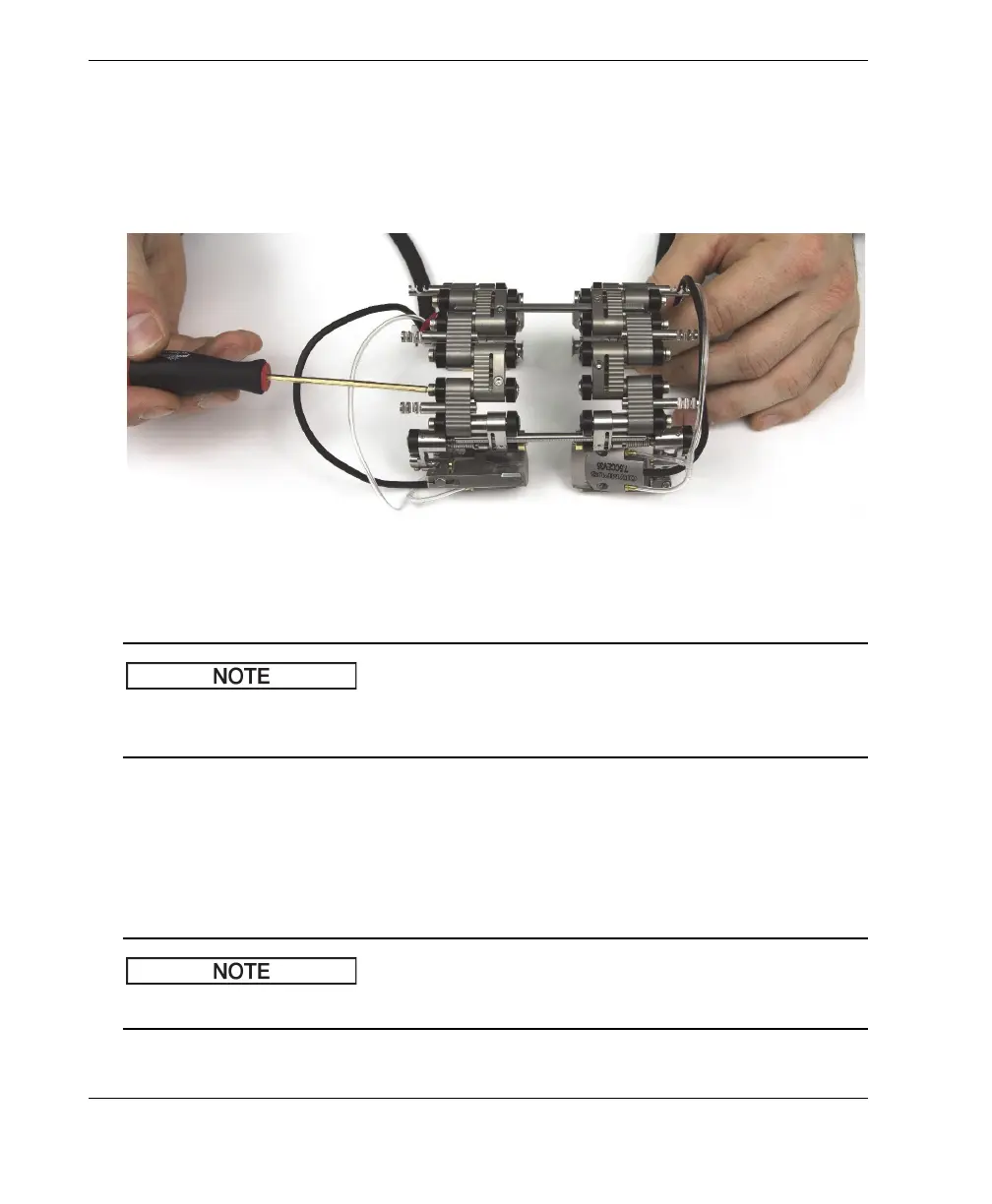
2. Loosen, by one turn, the self-captured pivot screws of the female links and, if
applicable, of the half links and medium links (see Figure 2-19 on page 36).
Figure 2-19 Loosening the links
If the joints do not rotate freely with the pivot screws loose, you may have to break
them loose by hand using a little force.
3. For single-probe scanning, you need to separate the two halves of the scanner (see
Figure 2-20 on page 37):
a) Loosen the crossbar screws of the encoder side.
b) Remove the other side of the scanner with the crossbars.
c) If applicable, remove the center crossbar.
For single-probe scanning, you must use the encoder side of the scanner.