DMTA-20006-01EN, Rev. B, February 2014
Setup and Operation
33
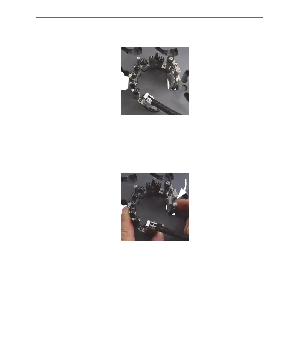
assembly in the pockets with one hand, firmly tighten all the pivot screws (see
Figure 2-15 on page 33).
Figure 2-15 Installing female and/or medium links
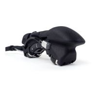
8. For setups on pipes with outside diameters larger than 33.4 mm (1.315 in.), rotate
the probe holder inward until the wedge touches the inside edge of the through-
hole portion of the template (see Figure 2-16 on page 33).
Figure 2-16 Rotating the probe holder to set the position for OD larger than
33.4 mm (1.315 in.)
9. For setups on pipes with small outside diameters ranging from 21.3 mm to
33.4 mm (0.840 in. to 1.315 in.), complete the following steps:
a) Lift the scanner slightly to the point where you can rotate the probe and
wedge inward.