DMTA-20006-01EN, Rev. B, February 2014
Setup and Operation
39
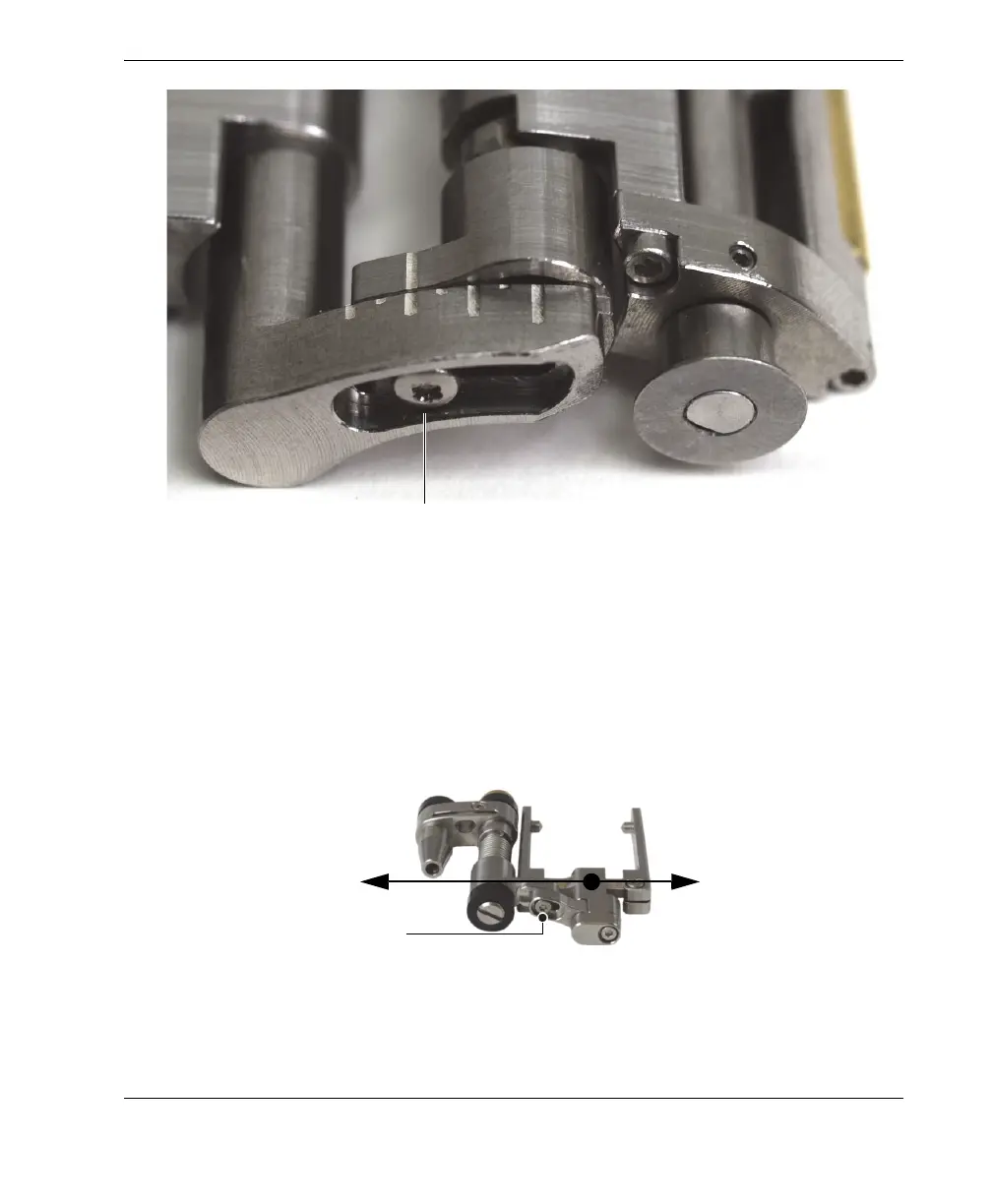
Figure 2-22 Example of tail configured to the 2.0 position
b) Retighten the tail-adjustment screw.
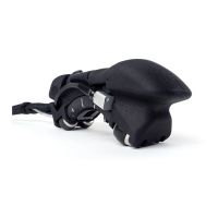
9. Configure the probe holder (see Figure 2-23 on page 39):
a) Loosen the probe-holder position screw.
b) Slide the probe holder to position noted in step 5.b, and then retighten the
probe-holder position screw.
Figure 2-23 The probe holder shown in the extended position
Tail-adjustment screw
1.0
1.5
2.0
2.5
3.0
3.5
4.0
Probe-holder position screw
Extended position
Retracted position