DMTA-20006-01EN, Rev. B, February 2014
Setup and Operation
31
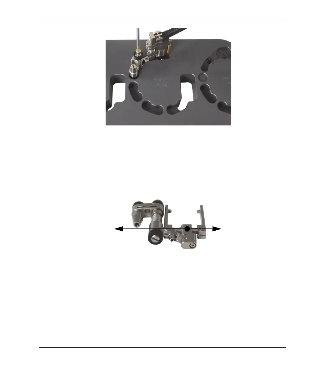
Figure 2-11 Installing the half-link
5. Configure the probe holder (see Figure 2-12 on page 31):
a) Loosen the probe-holder position screw.
b) Slide the probe holder to the position previously noted in step 2.b on page 28,
and then retighten the probe-holder position screw.
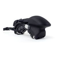
Figure 2-12 Adjusting the probe-holder position
c) Install the appropriate wedge and the probe on the probe support (see
section “Changing the Wedge” on page 25 for details), while ensuring that the
cable and tube are not twisted.
d) Adjust the length of the exposed cables and tubes, as needed (see
section “Adjusting the Length of Exposed Cables and Tubes” on page 26).
Probe-holder position screw
Extended position
Retracted position