DMTA-20006-01EN, Rev. B, February 2014
Specifications
63
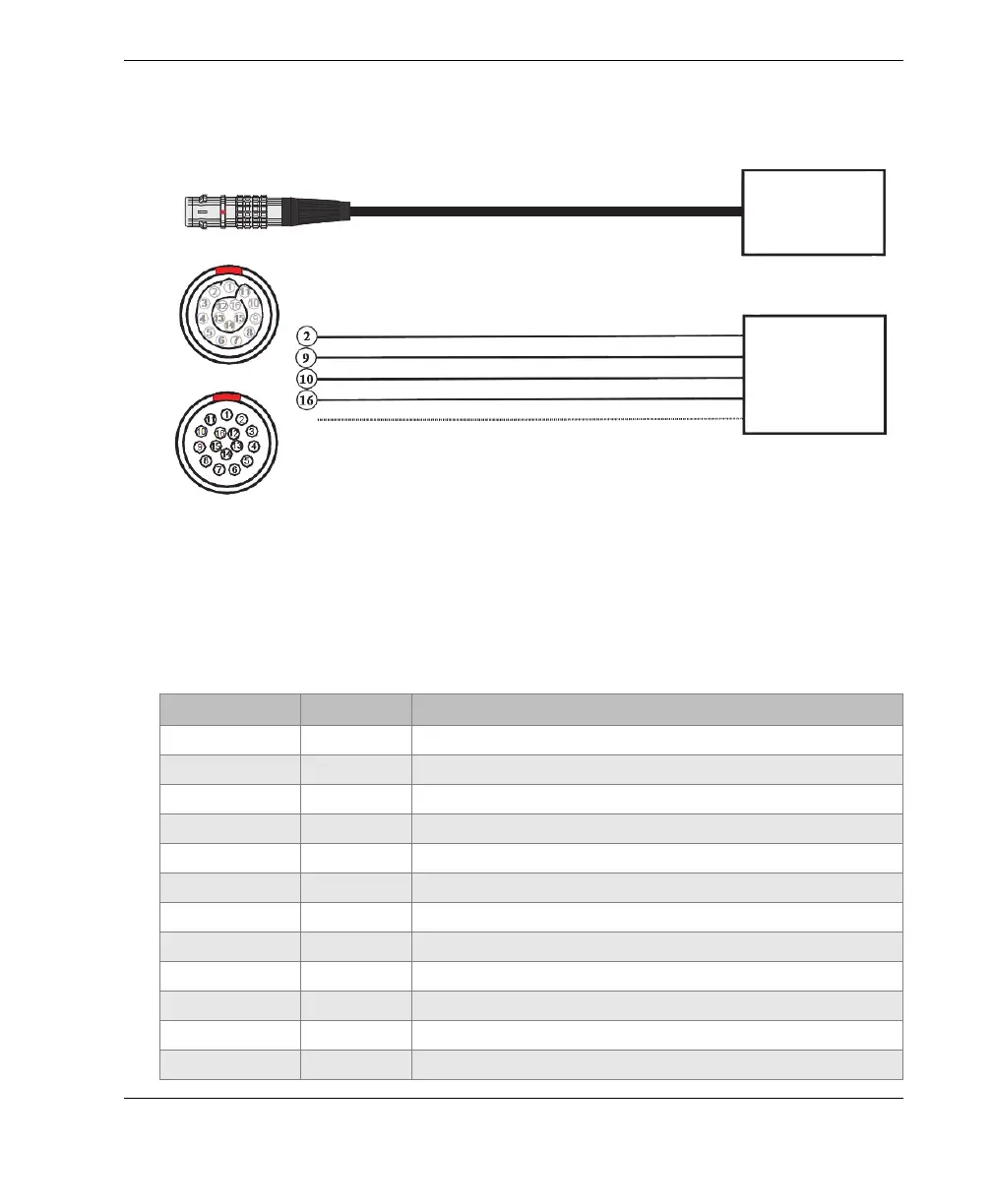
Figure 5-1 on page 63 and Table 13 on page 63 contain the pinout for the LEMO
connector used on the OmniScan MX2 model.
Figure 5-1 LEMO connector pinout diagram
Table 13 OmniScan MX2 pinout for the scanner interface
LEMO connector
Pin Signal Description
1N/ANot used
2 +5 V External power supply
3N/ANot used
4 N/A Not used
5N/ANot used
6 N/A Not used
7N/ANot used
8 N/A Not used
9 PhA axis 1 Encoder 1: phase A
10 PhB axis 1 Encoder 1: phase B
11 N/A Not used
12 N/A Not used
+5 V
PHA-1
PHB-1
GND
Shield
+5 V
PHA-1
PHB-1
GND
Shield
Case
Solder cup view
Contact view
COBRA
encoder
COBRA
encoder