DMTA-20006-01EN, Rev. B, February 2014
List of Figures
67
List of Figures
Figure i-1 Marking locations ................................................................................................ 1
Figure i-2 The OmniScan MX2 and the COBRA scanner .............................................. 13
Figure i-3 Operating the COBRA scanner in a limited access area .............................. 14
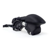
Figure 1-1 The COBRA scanner .......................................................................................... 15
Figure 1-2 Scanner component identification ................................................................... 16
Figure 1-3 Link types ........................................................................................................... 17
Figure 1-4 Pipe-to-component interface inspection with the one-sided scanner
configuration ...................................................................................................... 17
Figure 1-5 The setup templates .......................................................................................... 18
Figure 1-6 Tools included with the COBRA scanner ....................................................... 20
Figure 2-1 Removing the sleeve clamp .............................................................................. 22
Figure 2-2 Installing the protective sleeve ........................................................................ 23
Figure 2-3 Installing the sleeve clamp ............................................................................... 23
Figure 2-4 Installing the probe and the wedge on the scanner ...................................... 24
Figure 2-5 Changing the wedge on the scanner ............................................................... 25
Figure 2-6 Clipping the tube and the cable on the post .................................................. 27
Figure 2-7 The tail-adjustment screw ................................................................................ 28
Figure 2-8 Insert the tail in its setup template pocket ..................................................... 29
Figure 2-9 Tightening the tail-adjustment screw ............................................................. 29
Figure 2-10 Rotating the tail to the initial position ............................................................ 30
Figure 2-11 Installing the half-link ....................................................................................... 31
Figure 2-12 Adjusting the probe-holder position .............................................................. 31
Figure 2-13 Installing the probe holder into the setup template ..................................... 32
Figure 2-14 Installing male links .......................................................................................... 32
Figure 2-15 Installing female and/or medium links .......................................................... 33
Figure 2-16 Rotating the probe holder to set the position for OD larger
than 33.4 mm (1.315 in.) .................................................................................... 33
Figure 2-17 Rotating the probe holder to set position for OD smaller
than 33.4 mm (1.315 in.) .................................................................................... 34
Figure 2-18 Rotating the tail to set position for a small pipe setup ................................. 34