Chapter 2 Instrument Nomenclature
31
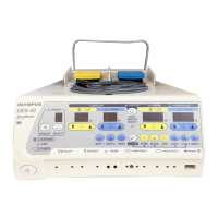
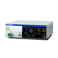
HIGH FLOW INSUFFLATION UNIT UHI-4
6. Caution lamp for excessive pressure
This lamp lights when the cavity pressure reaches 5 mmHg or more above
the set pressure.
7. Set/actual flow rate indicator
This indicator shows the set/actual flow rate.
The set value (green) is displayed while gas feed is stopped. When gas feed
starts, the measurement value (white) is displayed. The measurement value
display is switched to the set value display when the flow rate setting switch
or flow rate mode selector switch is pressed.
8. Caution lamp for tube obstruction
This lamp lights when the insufflation tube is kinked or clogged, or when
insufflation is performed into a very narrow space.
9. Volume indicator
This indicator shows the volume of gas used.
10. Lamp for insufflation start/stop indication
These lamps light when the corresponding insufflation action is selected.
11. Bar graph for flow rate
This graph shows the current flow rate.
12. Lamp for flow rate mode indication
These lamps light when the corresponding flow mode is selected.
13. Bar graph for measuring pressure
The cavity pressure level relative to the set pressure is displayed. The ninth
bar from the bottom corresponds to the set pressure. The bar corresponding
to the set pressure blinks.
14. Lamp for smoke evacuation mode indication
These lamps light when the corresponding smoke evacuation mode is
selected.
15. Lamp for cavity mode indication
These lamps light when the corresponding cavity mode is selected.
16. Bar graph for supply pressure
This bar graph shows the pressure in a CO
2
cylinder or a medical gas
pipeline connected to the device. An alarm and the yellow LED in the lowest
position are activated when no gas is delivered.
 Loading...