36
Chapter 3 Installation and Connection
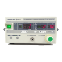
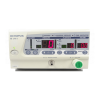
HIGH FLOW INSUFFLATION UNIT UHI-4
Chapter 3 Installation and Connection
Prepare the instrument and other compatible equipment (shown in “System
chart” in the Appendix) before each use.
Refer to the instruction manuals for each piece of equipment. Install and connect
all equipment as follows:
3.1 Installation workflow
Figure 3.1 shows the procedures for installation of this instrument and
accessories.
1. Install the main unit.
Refer to Section 3.2, “Installation of the UHI-4 main unit” on page 38.
2. Connect a CO
2
cylinder or a medical gas pipeline.
• CO
2
cylinder
Refer to Section 3.3 “Connecting a CO
2
cylinder” on page 39.
• Medical gas pipeline
Refer to Section 3.4, “Connecting the medical gas pipeline adapter (MAJ-1084/1085)” on
page 43.
3. Connect a foot switch.
Refer to Section 3.5, “Connecting the foot switch (MAJ-1939)” on page 44.
(The foot switch is optional. Connect it when using the smoke evacuation function.)
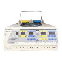
4. Connect an electrosurgical unit (ESG-400, UES-40) or a SonoSurg generator (USG-400,
SonoSurg-G2).
Refer to Section 3.6, “Connecting the electrosurgical unit (ESG-400, UES-40) or the SonoSurg generator
(USG-400, SonoSurg-G2)” on page 45.
(Connect it when used in combination.)
Next page
 Loading...
