28
Chapter 2 Instrument Nomenclature
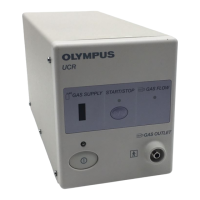
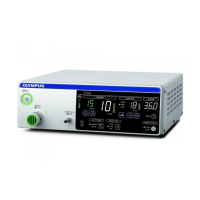
HIGH FLOW INSUFFLATION UNIT UHI-4
2.2 Front panel
Switches and connectors
1. Power switch
Press this switch to turn the power ON, and the power indicator around the
POWER switch lights. This switch is pressed again to turn the power OFF.
2. Pressure control switches
These switches are pressed to set the cavity pressure. The set value is
increased by pressing “+” and decreased by pressing “–”.
The setting range for each cavity mode is described below. The pressure
can be set in increments of 1 mmHg.
• “NORMAL” cavity mode: 3 – 25 mmHg
(To increase the pressure from 20 – 21 mmHg, keep pressing “+” for at
least 3 seconds.)
• “SMALL” cavity mode: 3 – 15 mmHg
3. Flow rate mode selector switch
Press this switch to select the flow rate mode. Each press of the switch
changes the mode as follows: LOW MED HIGH LOW.
1. Power switch
2. Pressure control
switches
3. Flow rate mode selector switch
4. Flow rate control switches
5. Volume reset switch
11. CO
2
suction control
pinch valve
10. CO
2
insufflation
connector
9. Display mode selector switch
8. Cavity mode selector switch
7. Smoke evacuation mode
selector switch
6. Insufflation switch
 Loading...