Chapter 2 Instrument Nomenclature
33
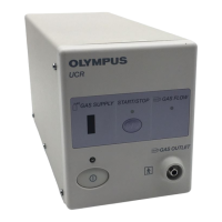
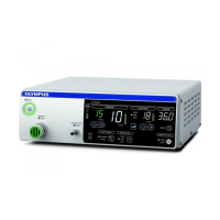
HIGH FLOW INSUFFLATION UNIT UHI-4
1. LINK-IN terminal
This terminal is provided for future connection of Olympus equipment. For
the equipment that can be combined with this instrument, refer to “System
chart” on page 143.
2. LINK-OUT terminal
This terminal is provided for future connection of Olympus equipment. For
the equipment that can be combined with this instrument, refer to “System
chart” on page 143.
3. Foot switch terminal
Connect the foot switch (MAJ-1939).
4. Potential equalization terminal
For safety purposes, this terminal is connected to a potential equalization
busbar of the electrical installation.
5. Fuse box
Stores the fuses that protect the instrument from electrical surges.
6. Power inlet
Connect the provided power cord to supply the AC power via this inlet.
7. CO
2
gas inlet
Connect a high-pressure hose (MAJ-1080) or a wall gas pipeline adapter
(MAJ-1084, MAJ-1085) or hose for cylinder (MAJ-1985, MAJ-1986).
 Loading...