• Even if you select MI1 to MI7 (General-purpose input 1 to 7) for the Multi-function Input S1 to
S7 Selection, you can select NO (NO contact) or NC (NC contact) for the Multi-function Input
S1 to S7 Operation Selection (C011 to C017).
• Even if you select MO1 to MO3 (General-purpose output 1 to 3) for the Multi-function Output
P1 and P2 Selection or for the Multi-function Relay Output (MA, MB) Function Selection, you
can select
NO (NO contact) or NC (NC contact)
for the Multi-function Output P1 and P2 Oper-
ation Selection (C031, C032) or for the Multi-function Relay Output (MA, MB) Operation
Selection (C036).
• In the Drive Programming, the analog I/O functions are allocated to XA(0), XA(1), YA(0) and
YA(1). You can monitor the analog I/O status in the programs by using these function vari-
ables regardless of the settings for A001, A201, C027 and C028.
• In the Drive Programming programs, you cannot monitor the status of multi-function I/O ter-
minals for which the general-purpose I/Os are not set in C001 to C007, C021, C022 or C026.
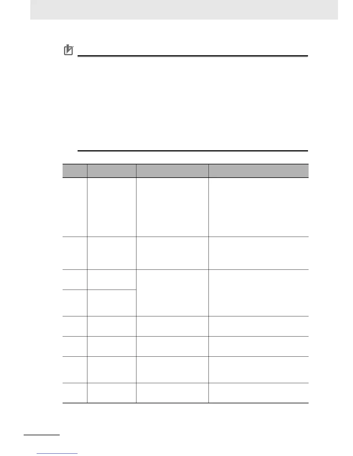
RX:
Parameter
No.
Function name Data Description
A001 Frequency Refer-
ence Selection
07: Drive Programming • Use this setting to specify the inverter fre-
quency reference by the function variables
of the Drive Programming.
• If you select any other option than 01
(Control circuit terminal block), the analog
inputs (FV, FI, FE) will be disconnected
from the frequency reference and you can
use them as the analog inputs XA(00) to
XA(02) for the Drive Programming.
C001 to
C008
Multi-function Input
S1 to S8 Selection
56 to 63: MI1 to MI8
(General-purpose
input 1 to 8)
• Set 56 to 63 (MI1 to MI8) to use the termi-
nals for the general-purpose inputs for the
Drive Programming.
• The parameter settings correspond to the
function variables X(00) to X(07).
C021 to
C025
Multi-function Output
P1 to P5 Selection
44 to 49: MO1 to MO6
(General-purpose
output 1 to 6)
• Set 44 to 49 (MO1 to MO6) to use the ter-
minals for the general-purpose outputs for
the Drive Programming.
C026 Multi-function Relay
Output (MA, MB)
Function Selection
• You can control the multi-function output
terminals by changing the corresponding
function variables Y(00) to Y(05) to
ON/OFF.
C027 MP Selection 12:
Drive Programming
(YA(0))
Set 12 (Drive Programming) to use the ter-
minal for the general-purpose pulse output
YA(0) for the Drive Programming.
C028 AM Selection 13:
Drive Programming
(YA(1))
Set 13 (Drive Programming) to use the ter-
minal for the general-purpose analog output
(voltage) YA(1) for the Drive Programming.
C029 AMI Selection 14:
Drive Programming
(YA(2))
Set 14 (Drive Programming) to use the termi-
nal for the general-purpose pulse analog out-
put (current) YA(2) for the Drive
Programming.
P031 Acceleration/Decel-
eration Time Input
Type
03: Drive Programming Set this parameter to control the
acceleration/deceleration time through the
Drive Programming.

 Loading...


