1035
3. Instructions
CS/CJ/NSJ Series Instructions Reference Manual (W474)
Failure Diagnosis Instructions
3
FPD
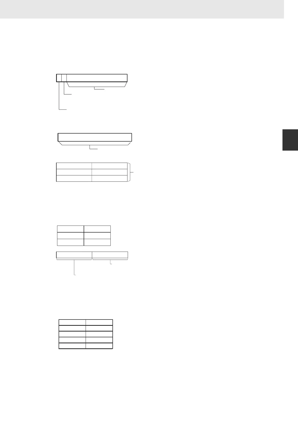
Bit Address and Message Output (C=8@@@)
When the leftmost digit of C is set to 8, the ASCII address of the input bit is output to R+2 to R+4. R
contains two flags which indicate whether an input bit has been found and whether it is used in a
normally open or normally closed input condition.
Register words R+2 through R+5 would have the following values for W51115.
D+6 to D+9
The user can store an ASCII message in register words R+6 to R+10. This message will be displayed
on the Programming Device if a non-fatal error is generated by the time monitoring function. Mark the
end of the message with the null character (00 hexadecimal).
15 014
R
13
15 0
R+1
Not possible to use.
Input type
0: Normally open
1: Normally closed
Bit Address Found Flag
0: Not found yet
1: Bit address found
Not possible to use.
D+2
D+3
D+4
815
07
Stores the bit number
A0.00 to A959.15
H0.00 to H511.15
W0.00 to W511.15
0.00 to 6143.15
TK0 to TK1023
_T0000 to _T4095
_C0000 to _C4095
Note The "_" represents an ASCII space.
15
R+2
R+3
R+4
W5
11
15
Bit address written in ASCII
D+5
Input type (hexadecimal)
30: Normally open
31: Normally closed
2D (hexadecimal)
8
15
07
15 8 07
R+6
R+7
R+8
R+9
R+10