135
3. Instructions
CS/CJ/NSJ Series Instructions Reference Manual (W474)
Notation and Layout of Instruction Descriptions
3
Notation and Layout of Instruction Descriptions
Instructions are described in groups by function. Refer to Appendix A List of Instructions by Function Code for a
list of instructions by mnemonic that lists the page number in this section for each instruction.
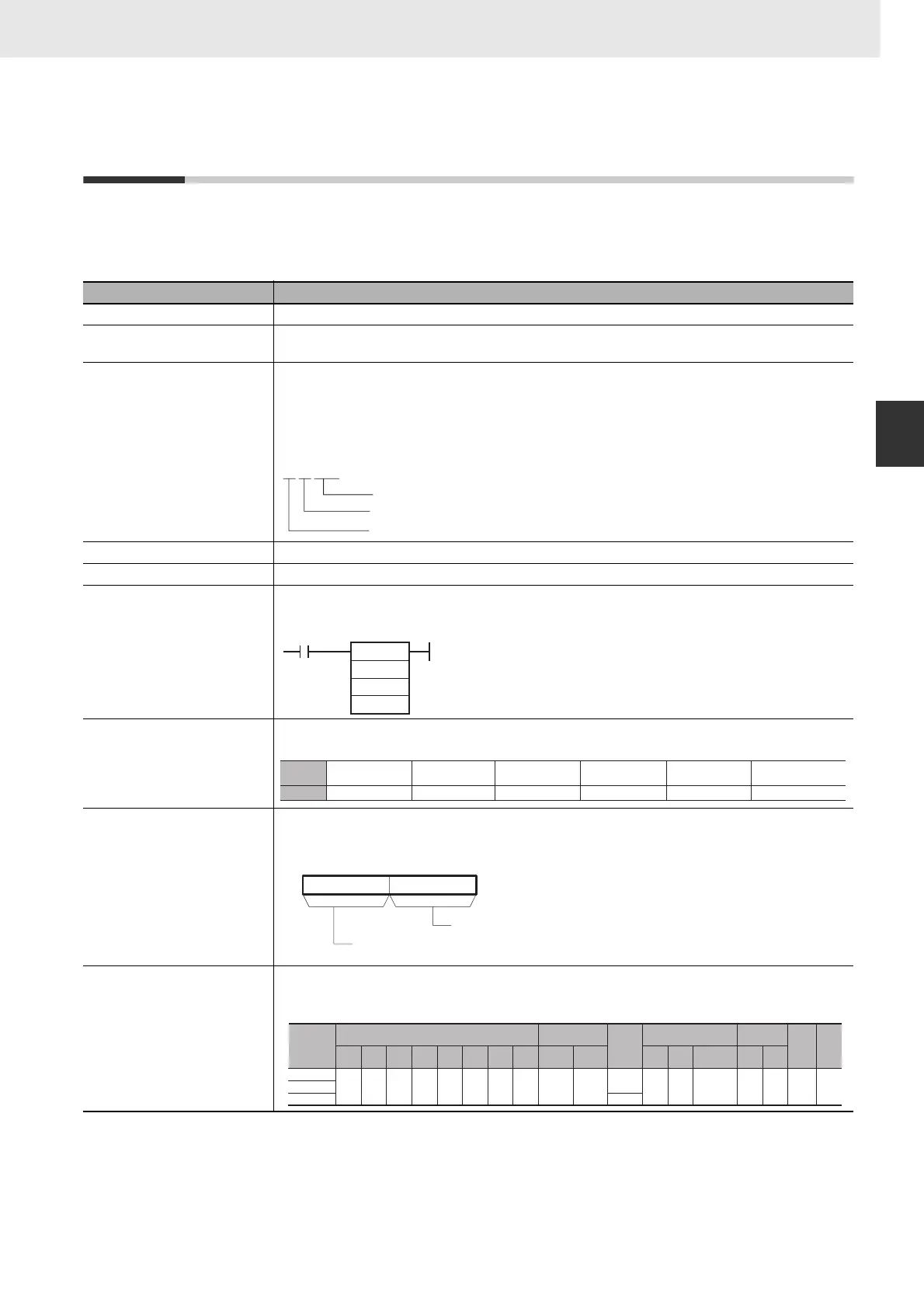
The description of each instruction is organized as described in the following table.
Item Contents
Instruction Indicates the name of the instruction. Example: MOVE BIT
Mnemonic Indicates the mnemonic.
Example: MOVB(082)
Variations Differentiation
@ Instruction that differentiates when the execution condition turns ON.
% Instruction that differentiates when the execution condition turns OFF.
Immediate refreshing
! Refreshes data in the I/O area specified by the operands or the Special I/O Unit words when the
instruction is executed.
Function code Indicates the function code.
Function The basic purpose of the instruction is described after the section heading.
Symbol The ladder symbol used to represent the instruction on the CX-Programmer is shown, as in the example
for the MOVE BIT instruction given below. The name of each operand is also provided with the ladder
symbol.
Applicable Program Areas The program areas in which the instruction can be used are specified. “OK” indicates the areas in which
the instruction can be used.
Operands Indicates a description of the operand, the data type, and the size.
Where necessary, the meaning of words and bits used in specific operands, such as control words, is
given.
Operand Specifications The memory areas addresses that can be used each operand are listed in a table like the following one.
The letters used in the column headings on the above are the same as those used in the ladder symbol.
“---” is used to indicate when an area cannot be specific for an operand.
Instruction (mnemonic)
Differentiation variation
Immediate refresh variation
MOV
@!
MOVB
S
C
D
S: Source word or data
C: Control word
D: Destination word
Area
Function block
definitions
Block program areas Step program areas Subroutines Interrupt tasks
SFC action or transition
programs
Usage OK OK OK OK OK OK
15 8 07
C
mn
Source bit: 00 to 0F
(0 to 15 decimal)
Destination bit: 00 to 0F
(0 to 15 decimal)
Area
Word addresses
Indirect DM/EM
addresses
Con-
stants
Registers Flags
Pulse
bits
TR
bits
CIO WR HR AR T C DM EM
@DM
@EM
*DM
*EM
DR IR
Indirect
using IR
TK CF
S
OK OK OK OK OK OK OK OK OK OK
OK
OK --- OK --- --- --- ---C
D ---