1. Basic Understanding of Instructions
2
CS/CJ/NSJ Series Instructions Reference Manual (W474)
1-1 Basic Understanding of Instructions
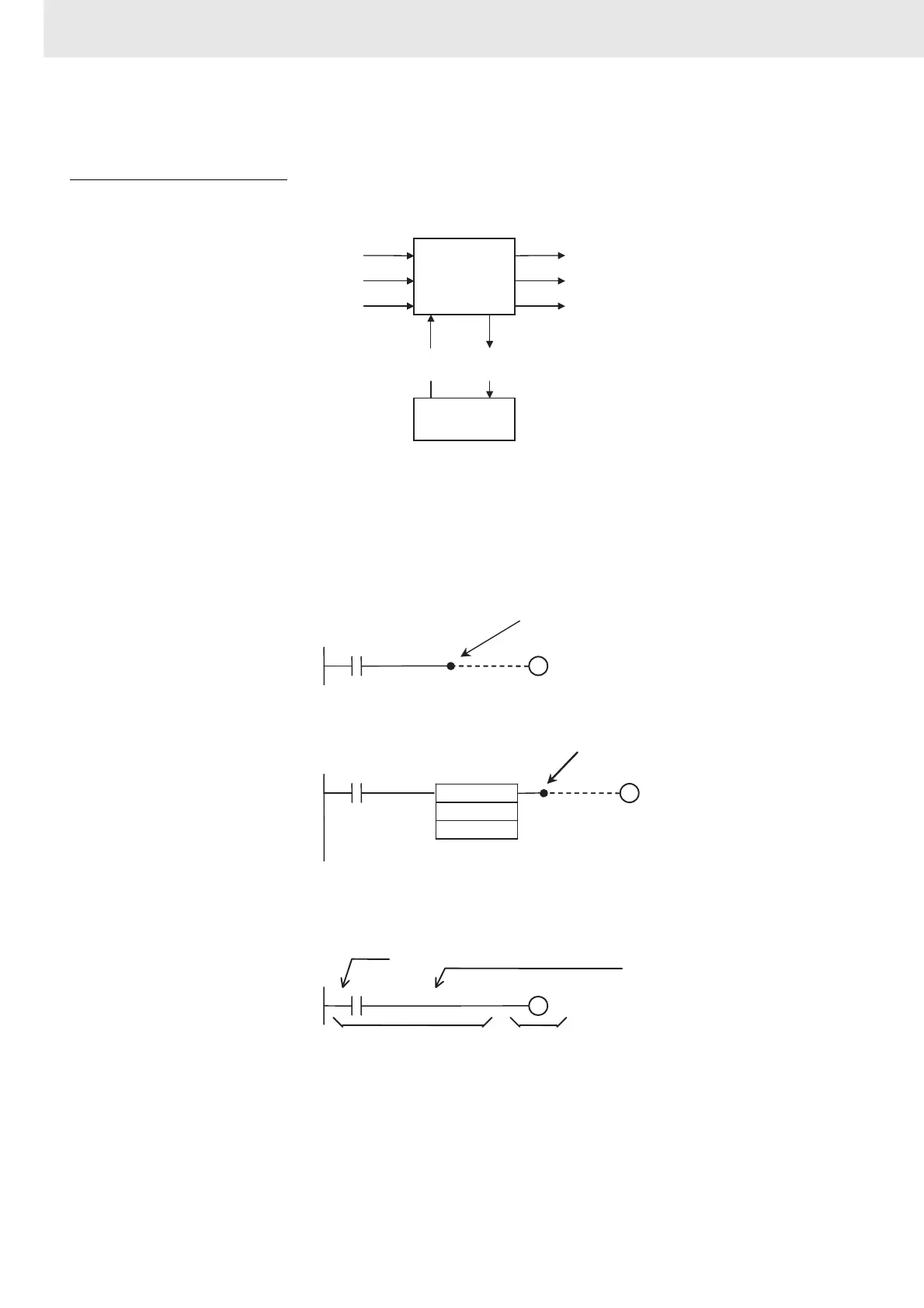
Structure of Instructions
Programs consist of instructions. The conceptual structure of the inputs to and
outputs from an instruction is shown in the following diagram.
Power Flow
The power flow is the execution condition that is used to control the execute
and instructions when programs are executing normally. In a ladder program,
power flow represents the status of the execution condition.
Input Instructions
• Load instructions indicate a logical start and outputs the execution condi-
tion.
• Intermediate instructions input the power flow as an execution condition
and output the power flow to an intermediate or output instruction.
Output Instructions
• Output instructions execute all functions, using the power flow as an exe-
cution condition.
Instruction Conditions
Instruction conditions are special conditions related to overall instruction exe-
cution that are output by the following instructions. Instruction conditions have
a higher priority than power flow (P.F.) when it comes to deciding whether or
not to execute an instruction. An instruction may not be executed or may act
differently depending on instruction conditions. Instruction conditions are
reset (canceled) at the start of each task, i.e., they are reset when the task
changes.
Flags
Instruction
Flag
Power flow (P.F., execution condition)
Instruction condition
Power flow (P.F., execution condition)
*
1
Instruction condition
*
2
Operands
(sources)
Operands
(destinations)
I/O memory
*1: Input instructions only.
*2: Not output for all instructions.
Outputs the execution
condition.
=
D0
#1215
Outputs the execution
condition.
Input block
Output block
Power flow for
output instruction
LD power flow