667
3. Instructions
CS/CJ/NSJ Series Instructions Reference Manual (W474)
Data Control Instructions
3
TPO
In this case, set the same value for the PID Control instruction’s output range and the TPO(685)
instruction’s manipulated variable range. For example, when the PID Control instruction’s output range
and the TPO(685) instruction’s manipulated variable range are both set to 12 bits (0000 to 0FFF hex),
the duty ratio is calculated by dividing the manipulated variable from the PID Control instruction by
0FFF hex and TPO(685) converts that duty ratio to a time-proportional output.
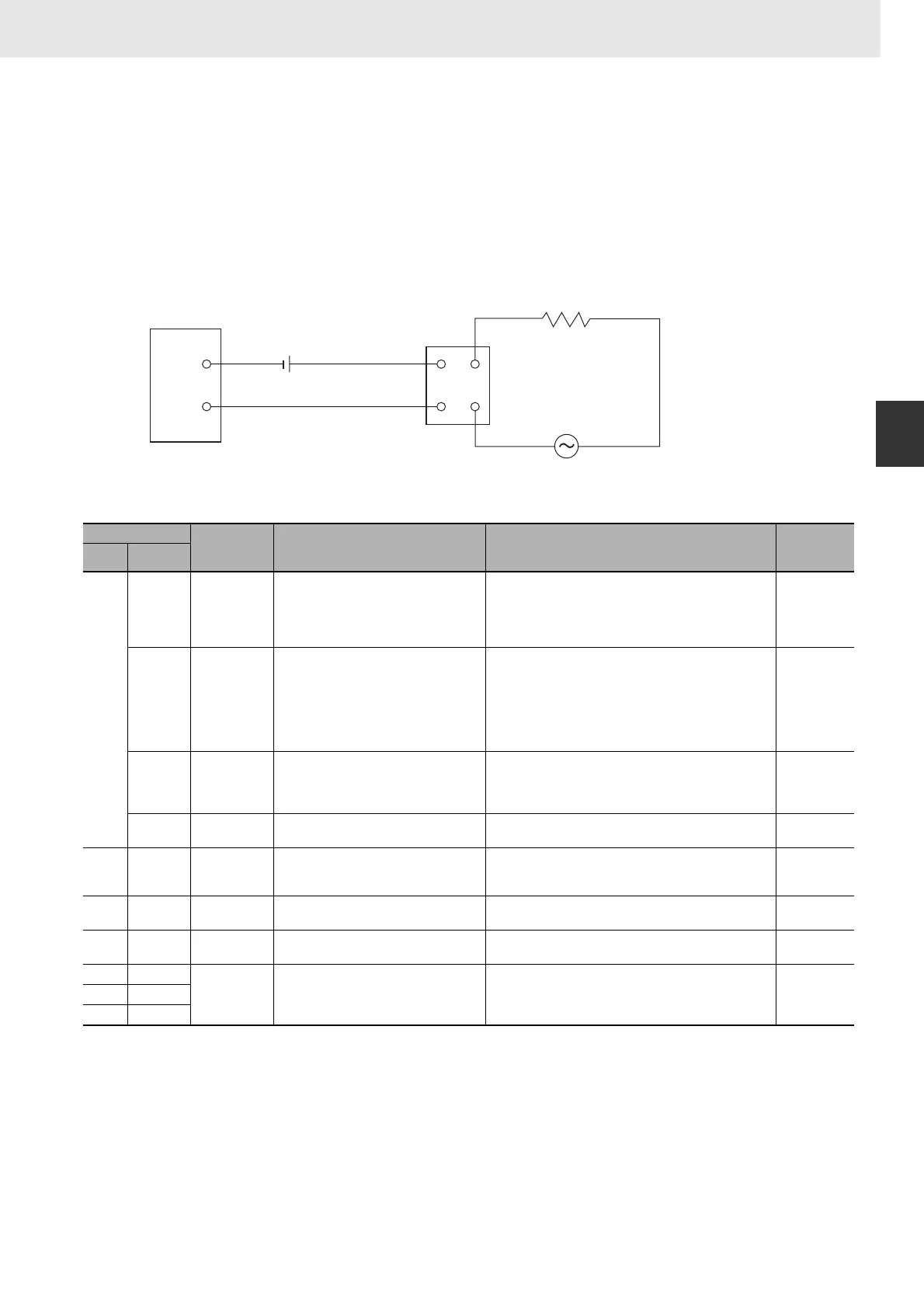
z External Wiring Example
Connect the Transistor Output Unit to a solid state relay (SSR) as shown in the following diagram.
Parameter Settings
Note When the output limit control function is enabled, set the lower and upper limits as follows:
0000 hex ≤ lower limit ≤ upper limit ≤ 2710 hex.
Execution
• The instruction is executed while the input condition is ON.
• When instruction execution starts, the output bit (R) is turned ON/OFF according to the duty ratio.
• The parameters (in C to C+3) are read in real time each time that the instruction is executed. When
changing the parameters, change all of them at the same time so that different sets of parameters are
not mixed.
Control data
Item Contents Setting range
Change with
ON input
condition
Word Bits
C 00 to 03 Manipulated
variable range
Specifies the number of input data bits. 0 hex: 8 bits 5 hex: 13 bits
1 hex: 9 bits 6 hex: 14 bits
2 hex: 10 bits 7 hex: 15 bits
3 hex: 11 bits 8 hex: 16 bits
4 hex: 12 bits
Allowed
04 to 07 Input type Specifies whether S contains a duty ratio
or manipulated variable.
0 hex: Duty ratio
Setting range for S: 0000 to 2710 hex (0.00 to
100.00%)
1 hex: Manipulated variable
Setting range for S: 0000 to FFFF hex (0 to 65,535)
(The maximum setting depends on the MV range
set with bits 00 to 03 of C.)
Allowed
08 to 11 Input read
timing
Specifies the input read timing. 0 hex: Use the beginning value of the control period
1 hex: Use lower value
2 hex: Use higher value
3 hex: Continuous adjustment
Allowed
12 to 15 Output limit
control
Specifies whether the output limit function
is enabled or disabled.
0 hex: Disabled
1 hex: Enabled (See note.)
Allowed
C+1 00 to 15 Control period Control period
(Time period in which the ON/OFF
changes are made.)
0064 to 270F hex (1.00 to 99.99 s)
Note: For example, 1.00 s is set as 0064 hex, and not
0001 hex.
Allowed
C +2 00 to 15 Output lower
limit
Specifies the lower limit when the output
limit is enabled.
0000 to 2710 hex (0 to 100.00%) Allowed
C +3 00 to 15 Output upper
limit
Specifies the upper limit when the output
limit is enabled.
0000 to 2710 hex (0 to 100.00%) Allowed
C+4 00 to 15 Work area This work area is used by the system. It
cannot be used by the user.
Cannot be used. ---
C+5 00 to 15
C+6 00 to 15
COM
SSR
AC
+
−
Transistor Output Unit
Heater
12 to 24 VDC