3. Instructions
666
CS/CJ/NSJ Series Instructions Reference Manual (W474)
R: Pulse Output Bit
Specifies the destination output bit for the pulse output.
Normally, specify an output bit allocated to a Transistor Output Unit and connect a solid state relay to
the Transistor Output Unit.
z Operand Specifications
Flags
Function
Receives a duty ratio or manipulated variable input from the word address specified by S, converts the
duty ratio to a time-proportional output (see note) based on the parameters specified in words C to C+3,
and outputs a pulse output to the bit specified by R.
Note A time-proportional output is changed proportionally based on the ON/OFF ratio in input word S. The period
in which the ON and OFF status changes is known as the control period and is set in parameter word C+1.
Example: When the control period is 1 s and the input value is 50%, the bit is ON for 0.5 s and OFF for 0.5 s.
When the control period is 1 s and the input value is 80%, the bit is ON for 0.8 s and OFF for 0.2 s.
Generally, TPO(685) is used together with PID(190) or PIDAT(191) and the PID instruction’s
manipulated variable result word (D) is specified as the input word (S) for the TPO(685) instruction.
Also, an output bit allocated to a Transistor Output Unit is generally specified as R and a solid state
relay is connected to the Transistor Output Unit to perform time-proportional control of a heater
(proportional control of the ON/OFF ratio).
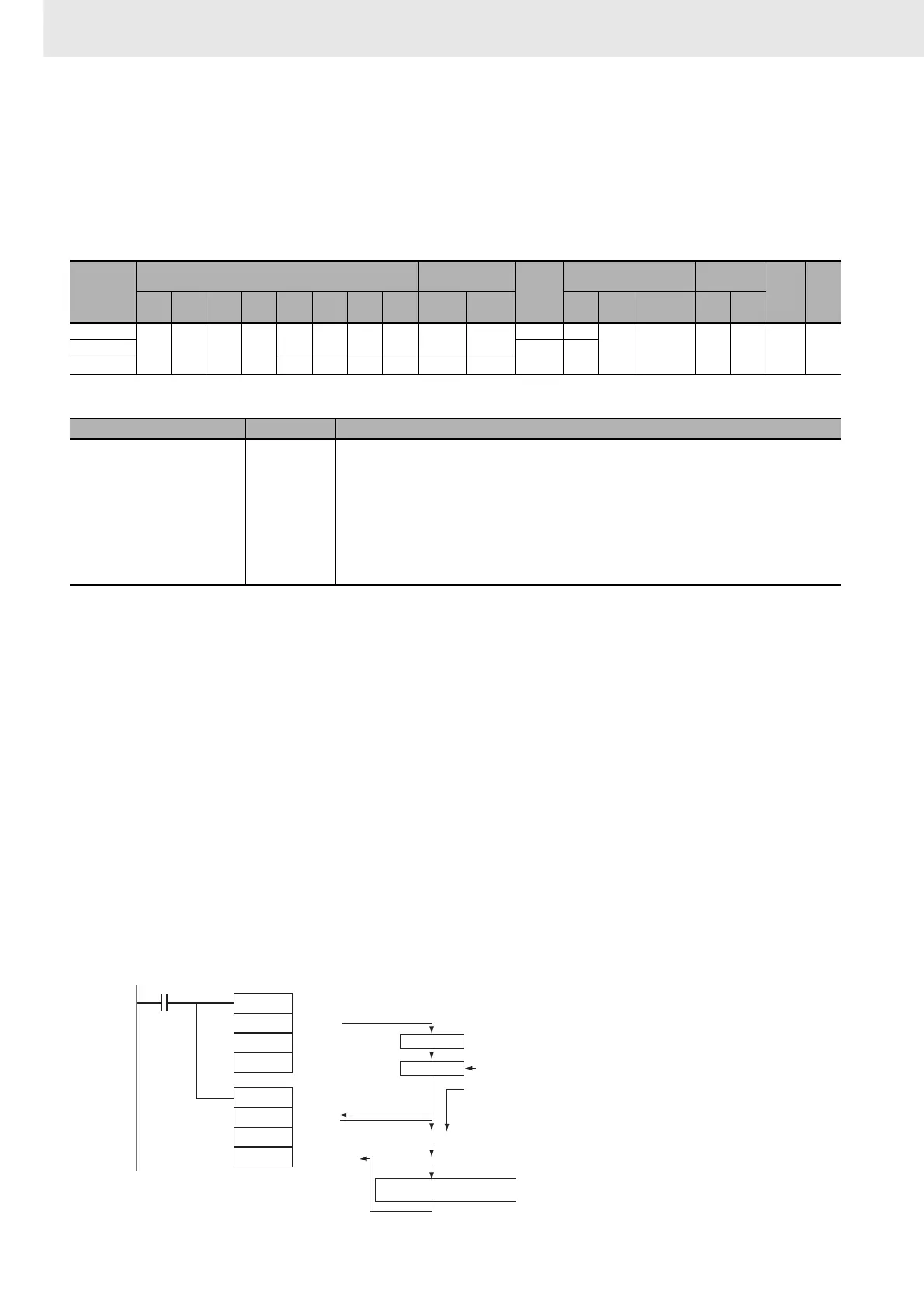
z Combining TPO(685) with a PID Control Instruction
When combining TPO(685) with a PID control instruction, the manipulated variable input is divided by
the manipulated variable range to calculate the duty ratio, that duty ratio is converted to a time-
proportional output, and pulses are output.
Area
Word addresses
Indirect DM/EM
addresses
Con-
stants
Registers Flags
Pulse
bits
TR
bits
CIO WR HR AR T C DM EM
@DM
@EM
*DM
*EM
DR IR
Indirect
using IR
TK CF
S
OK OK OK OK
OK OK OK OK OK OK
OK OK
--- OK --- --- --- ---C
--- ---
R --- --- --- --- --- ---
Name Label Operation
Error Flag P_ER • ON if the input data in S is out of range. (The input data setting range depends on the input type set-
ting.)
• ON if the C data is out of range. (The manipulated variable range will cause an error only when the
input type is set to manipulated variable.)
• ON if the control period in C+1 is out of range.
• ON if the output limit function is enabled but the output lower limit (C+2) or output upper limit (C+3) is
out of range.
• ON if the output limit function is enabled but the output lower limit (C+2) is less than or equal to the
output upper limit (C+3).
• OFF in all other cases.
0.00
PID
S
C
D0
TPO
D0
C
R
MV
D0
PV input
PID parameters
MV
Parameters
Pulse output
Manipulated variable (MV)
Output range
= MV range
MV ÷ MV range
Duty ratio (0.00% to 100.00%)
Manipulated
variable
PID calculation
Conversion to time-proportional
output