3. Instructions
856
CS/CJ/NSJ Series Instructions Reference Manual (W474)
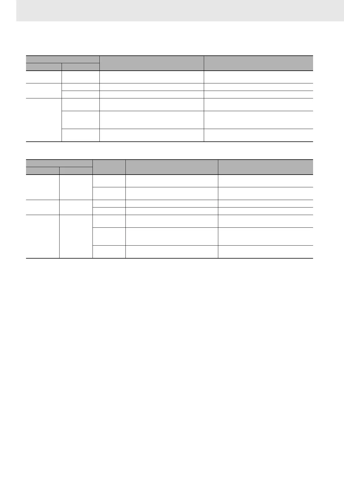
z PLC Setup Settings
z DM Setup Area Settings for Serial Communication Board's Ports
Function
• TXD(236) reads N bytes of data from words S to S+(N÷2)-1 and outputs the raw data in no-protocol
mode from the CPU Unit's built-in RS-232C port or one of the Serial Communications Board's serial
ports. (The output port is specified with bits 8 to 11 of C.)
The start and end codes specified for no-protocol mode are added to the data before the data is
output. The start and end codes are specified in the PLC Setup (for the CPU Unit's RS-232C port) or
the allocated DM Setup Area (for the Serial Communications Board's ports).
• The following send-message frame format can be set in the PLC Setup (for the CPU Unit's RS-232C
port) or the allocated DM Setup Area (for the Serial Communications Board's ports).
1) Start code: None or 00 to FF hex.
2) End code: None, CR+LF, or 00 to FF hex.
The data will be sent with any start and/or end codes specified in the PLC Setup or the allocated DM
Setup Area. If start and end codes are specified, the codes will be added to the send data (N). In this
case, the maximum number of bytes that can be specified for N is 256 bytes.
• Data is sent in the order specified in C.
• If RS signal control is specified in C, bit 15 of S will be used as the RS signal.
• If ER signal control is specified in C, bit 15 of S will be used as the ER signal.
If RS and ER signal control is specified in C, bit 15 of S will be used as the RS signal and bit 14 of S
will be used as the ER signal.
If 1, 2, or 3 hex is specified for RS and ER signal control in C, TXD(236) will be executed regardless
of the status of the Send Ready Flag (A392.05, A356.05, or A356.13 depending on the port being
used).
• Up to 259 bytes can be sent, including the send data (N = 256 bytes max.), the start code, and the
end code.
• Specify the size of the send data, not including the start code and end code, in N.
Programming Console address
Name Settings
Word Bit
162 0 to 15
No-protocol Mode Send Delay 0000 to 210F hex,
0 to 99,990 ms decimal (in 10-ms units)
164
8 to 15 No-protocol Mode Start Code 00 to FF hex
0 to 7 No-protocol Mode End Code 00 to FF hex
165
12
No-protocol Mode Start Code Specifier 0: None
1: Use start code.
8 and 9
No-protocol Mode End Code Specifier 0 hex: None
1 hex: Use end code.
2 hex: Use CR+LF.
0 to 7
No-protocol Mode Number of Bytes of Data 00 hex: 256 bytes (default)
01 to FF hex: 1 to 255 bytes
Setup Area word
Bit Name Settings
Port 1 Port 2
D32002 D32012
15
No-protocol Mode Send Delay Specifier 0: Default (0 ms)
1: Use delay in bits 1 to 14.
0 to 14
No-protocol Mode Send Delay Time 0000 to 7530 hex
0 to 300,000 ms decimal (in 10-ms units)
D32004 D32014
8 to 15 No-protocol Mode Start Code 00 to FF hex
0 to 7 No-protocol Mode End Code 00 to FF hex
D32005 D32015
12 to 15
No-protocol Mode Start Code Specifier 0 hex: None
1 hex: Use start code.
8 to 11
No-protocol Mode End Code Specifier 0 hex: None
1 hex: Use end code.
2 hex: Use CR+LF.
0 to 7
Number of Bytes of Data 00 hex: 256 bytes (default)
01 to FF hex: 1 to 255 bytes