655
3. Instructions
CS/CJ/NSJ Series Instructions Reference Manual (W474)
Data Control Instructions
3
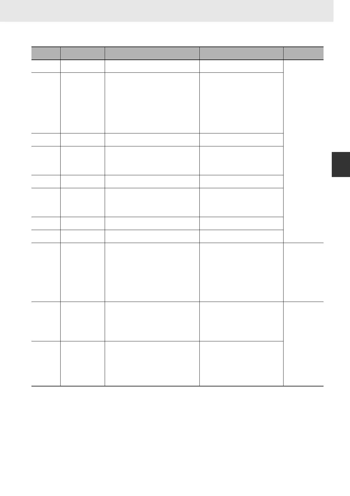
PIDAT
Note 1 When the unit is designated as 1, the range is from 1 to 8,191 times the period. When the unit is designated as 9, the
range is from 0.1 to 819.1 s. When 9 is designated, set the integral and derivative times to within a range of 1 to 8,191
times the sampling period.
2 Setting the 2-PID parameter (α) to 000 yields 0.65, the normal value.
3 When the manipulated variable output limit control is enabled (i.e., set to “1”), set the values as follows:
0000 ≤ MV output lower limit ≤ MV output upper limit ≤ Max. value of output range
Bit 00 of C+5 PID forward/reverse
designation
Determines the direction of the proportional
action.
0: Reverse action
1: Forward action
Not allowed
Bits 13 to 14
of C+6
ID starting integral
manipulated variable
designation (unit
version 4.0 or later
only)
Determines the initial integral manipulated
variable when PID control is started (i.e., when
the input turns ON) .
Bit 14 = 0 and bit 13=0:
Start from same integral manipulated value
as manipulated variable output designation
(Pre-Ver. 4.0 operation).
Bit 14 = 0 or 1 and bit 13 = 1:
Bumpless operation (i.e., start from an
integral manipulated variable that will not
abruptly change the manipulated variable
output and result in a continuous change).
Bit 14 = 1 and bit 13 = 0:
Start with integral manipulated variable = 0.
Bit 12 of C+6 Manipulated variable
output limit control
Determines whether or not limit control will apply
to the manipulated variable output.
0: Disabled (no limit control)
1: Enabled (limit control)
Bits 08 to 11
of C+6
Input range The number of input data bits. 0: 8 bits 5: 13 bits
1: 9 bits 6: 14 bits
2: 10 bits 7: 15 bits
3: 11 bits 8: 16 bits
4: 12 bits
Bits 04 to 07
of C+6
Integral and
derivative unit
Determines the unit for expressing the integral
and derivative constants.
1: Sampling period multiple
9: Time (unit: 100 ms)
Bits 00 to 03
of C+6
Output range The number of output data bits. (The number of
output bits is automatically the same as the
number of input bits.)
0: 8 bits 5: 13 bits
1: 9 bits 6: 14 bits
2: 10 bits 7: 15 bits
3: 11 bits 8: 16 bits
4: 12 bits
C+7 Manipulated variable
output lower limit
The lower limit for when the manipulated variable
output limit is enabled.
0000 to FFFF (binary)
(See note 3.)
C+8 Manipulated variable
output upper limit
The upper limit for when the manipulated variable
output limit is enabled.
0000 to FFFF (binary)
(See note 3.)
Bit 15 of C+9 AT Command Bit This control bit starts autotuning.
• Set the AT Command Bit to 1 to perform auto-
tuning. (Autotuning can be started while
PIDAT(191) is being executed.)
• This bit is turned OFF automatically when auto-
tuning is completed.
Autotuning will be interrupted if the AT Command
Bit is turned OFF manually. In this case, the PID
constants will be enabled if they were already
calculated when autotuning was interrupted.
As a Control Bit:
•0
→ 1:
Executes autotuning.
•1
→ 0:
Interrupts autotuning.
(PID(191) turns the bit OFF automatically
when autotuning is completed.
As a Flag:
0: Autotuning is not being executed.
1: Autotuning is being executed.
Allowed
Bits 00 to 11
of C+9
AT Calculation Gain Set this parameter to adjust the contribution of the
PID calculation results to the stored values.
Normally, leave this parameter set to its default
(0000).
• Increase the value when emphasizing stability.
• Decrease the value when emphasizing respon-
siveness.
0000 hex: 1.00 (Default)
0001 to 03E8 hex (1 to 1000);
(0.01 to 10.00, in units of 0.01)
Allowed
(These parameters
are read when
autotuning starts.)
C+10 Limit-cycle Hysteresis Sets the hysteresis when the limit cycle is
generated. The default setting for reverse
operation turns ON the MV with a hysteresis of
SV−20%.
Increase this setting if a proper limit cycle cannot
be generated because the PV is unstable.
However, the AT accuracy will decline if the Limit-
cycle Hysteresis is higher than necessary.
0000 hex: 0.20% (Default)
0001 to 03E8 hex:
0.01 to 10.00% in units of 0.01%
FFFF hex: 0.00%
Note The percentage is with respect to the
input range.
Control data Item Contents Setting range
Change with ON
input condition