809
3. Instructions
CS/CJ/NSJ Series Instructions Reference Manual (W474)
Basic I/O Unit Instructions
3
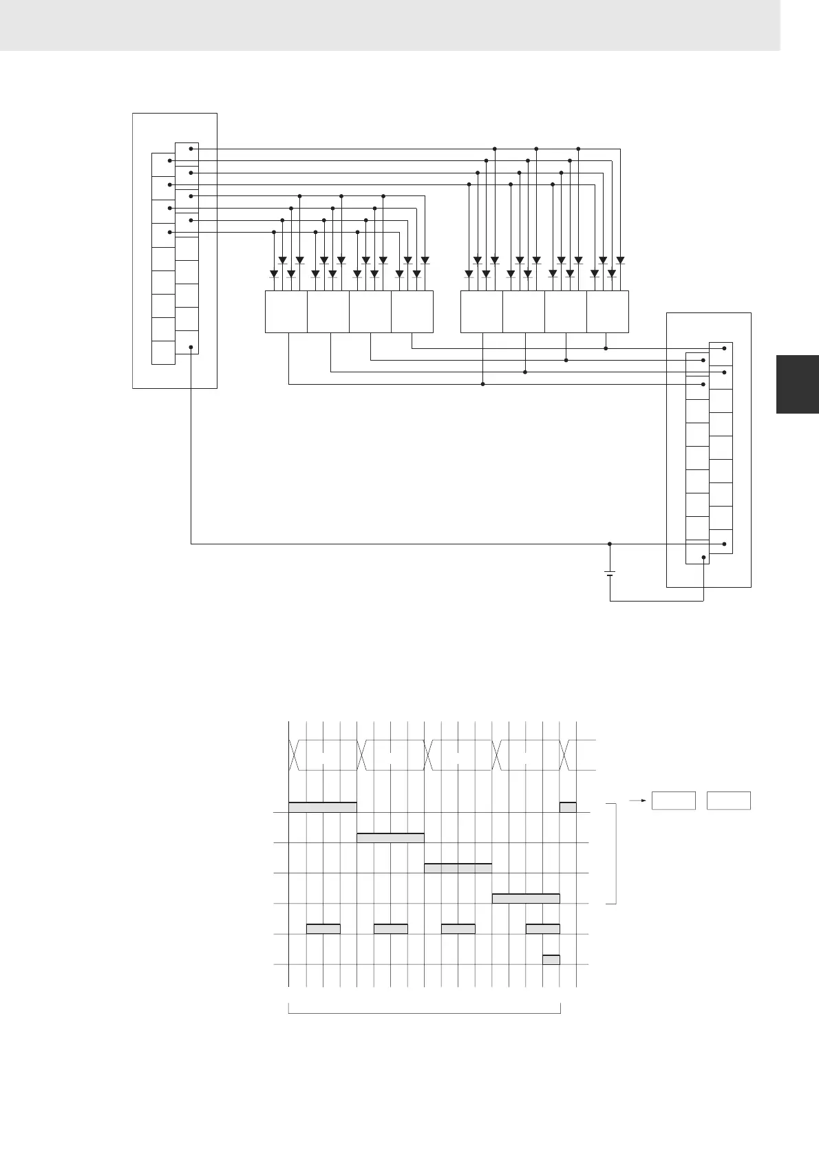
DSW
The inputs and outputs can be connected to the following kinds of Basic I/O Units and High-density I/O
Units as long as they are not mounted in a SYSMAC BUS Remote I/O Rack.
• DC Input Units with 8 or more input points
• Transistor Output Units with 8 or more output points
z Timing Chart
1
3
5
7
9
11
13
15
COM
0
2
4
6
8
10
12
14
COM
ID212
1
3
5
7
9
11
13
15
COM
0
2
4
6
8
10
12
14
DC
OD212
1248
76 5 4 321C
Input Unit
Switch no. 8
Output Unit
Note The data read signal is not connected in this example.
A7B
Thumbwheel
Switch
00
01
02
03
04
05
O
10
0
10
1
10
2
10
3
D+1 D
0 1 2 3 4 5 6 7 8 9 10 11 12 13 14 15 16
I
Leftmost
4 digits
Rightmost
4 digits
Input data
CS signals
One Round Flag
RD (read) signal
16 cycles to complete one round of execution
Eight digits: 00 to 03, 04 to 07
Four digits: 00 to 03
When only 4 digits are
only word D is used.