863
3. Instructions
CS/CJ/NSJ Series Instructions Reference Manual (W474)
Serial Communications Instructions
3
RXD
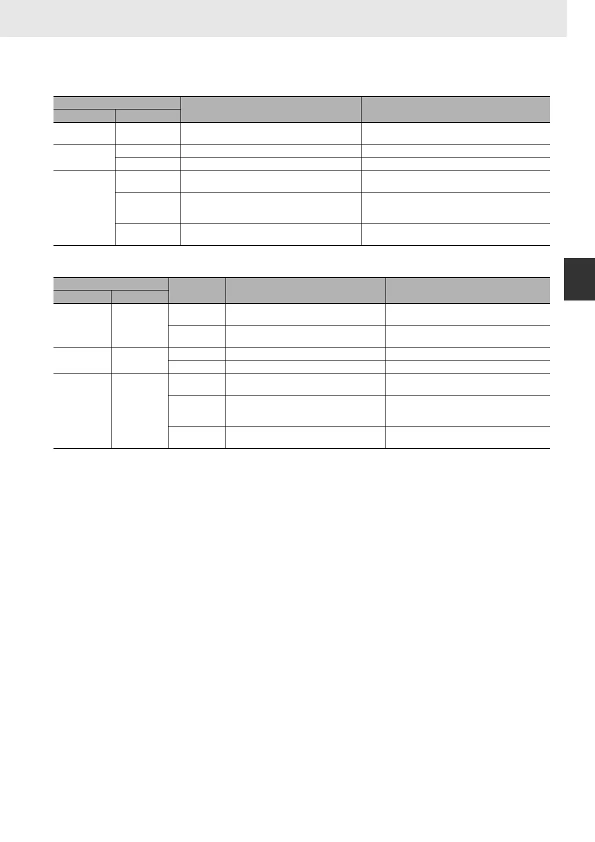
z PLC Setup Settings for CPU Unit's RS-232C Port
z DM Setup Area Settings for Serial Communication Board's Ports
Function
• RXD(235) reads data that has been received in no-protocol mode at the CPU Unit's built-in RS-232C
port or one of the Serial Communications Board's serial ports (the port is specified with bits 8 to 11 of
C) and stores N bytes of data in words D to D+(N÷2)-1. If N bytes of data has not been received at
the port, then only the data that has been received will be stored.
• The following receive message frame format can be set in the PLC Setup (for the CPU Unit's RS-
232C port) or the allocated DM Setup Area (for the Serial Communications Board's ports).
1) Start code: None or 00 to FF hex
2) End code: None, CR+LF, or 00 to FF hex. If no end code is specified, the number of bytes to
received is set from 00 to FF hex (1 to 256 decimal; 00 specifies 256 bytes).
• Data will be stored in memory in the order specified in C.
• Cases where the reception completion flag turns ON
The Reception Completed Flag (note (a)) will turn ON when the number of bytes specified in the
PLC Setup (for the CPU Unit's RS-232C port) or the allocated DM Setup Area (for the Serial
Communications Board's ports) has been received. When the Reception Completed Flag turns ON,
the number of bytes in the Reception Counter (note (b)) will have the same value as the number of
receive bytes specified in the PLC Setup or the allocated DM Setup Area. If more bytes are received
than specified, the Reception Overflow Flag (note (c)) will turn ON.
If an end code is specified in the PLC Setup or the allocated DM Setup Area, the Reception
Completed Flag (note (a)) will turn ON when the end code is received or when 256 bytes of data
have been received.
• Reception will be stopped if 259 bytes of data are received. If more data is input after that, the
Overrun Error Flag (note (e)) and Transmission Error Flag (note (f)) will turn ON. If an overrun error,
framing error, or parity error occurs on the CPU Unit's built-in serial port, serial port reception will
stop. The serial port must be restarted to begin reception again.
Programming Console address
Name Settings
Word Bit
162 0 to 15
No-protocol Mode Send Delay 0000 to 210F hex,
0 to 99,990 ms decimal (in 10-ms units)
164
8 to 15 No-protocol Mode Start Code 00 to FF hex
0 to 7 No-protocol Mode End Code 00 to FF hex
165
12
No-protocol Mode Start Code Specifier 0: None
1: Use start code.
8 and 9
No-protocol Mode End Code Specifier 0 hex: None
1 hex: Use end code.
2 hex: Use CR+LF.
0 to 7
No-protocol Mode Number of Bytes of Data 00 hex: 256 bytes (default)
01 to FF hex: 1 to 255 bytes
Setup Area word
Bit Name Settings
Port 1 Port 2
D32002 D32012
15
No-protocol Mode Send Delay Specifier 0: Default (0 ms)
1: Use delay in bits 1 to 14.
0 to 14
No-protocol Mode Send Delay Time 0000 to 7530 hex
0 to 300,000 ms decimal (in 10-ms units)
D32004 D32014
8 to 15 No-protocol Mode Start Code 00 to FF hex
0 to 7 No-protocol Mode End Code 00 to FF hex
D32005 D32015
12 to 15
No-protocol Mode Start Code Specifier 0 hex: None
1 hex: Use start code.
8 to 11
No-protocol Mode End Code Specifier 0 hex: None
1 hex: Use end code.
2 hex: Use CR+LF.
0 to 7
Number of Bytes of Data 00 hex: 256 bytes (default)
01 to FF hex: 1 to 255 bytes