3. Instructions
868
CS/CJ/NSJ Series Instructions Reference Manual (W474)
Programming Example
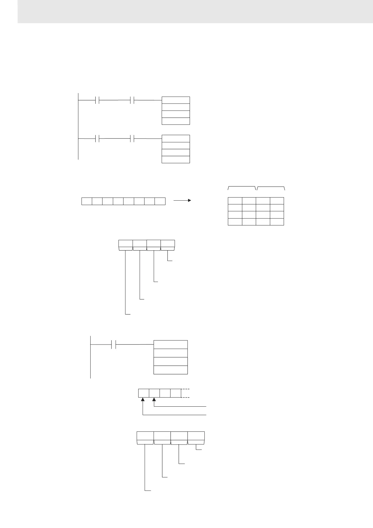
If CIO 0.02 turns ON while the RS-232C Port Send Ready Flag (A392.05) is ON, the number of bytes of
reading results specified in the RS-232C Port Reception Counter (A393) are read from the Code
Reader connected to the CPU Unit's built-in RS-232C port and stored starting from the upper byte of
D100.
Controlling Signals
2 F 03
3 0 63
15 8 71112 340
S: D100
TXD
D10
D20
0.01 A392.05
S
C
&3
N
D101
RXD
D100
D20
0.02 A392.06
A393
0 0 00
15 8 71112 340
C: D20
D102
3 8 F2
D103
3 1 13
=”06/08/11
Received
30 36 2F 30 38 2F 31 31
RS-232C Port Send
Ready Flag
RS-232C Port Receive
Ready Flag
RS-232C Port
Reception Counter
Always #0.
Serial Port Specifier
#0: CPU Unit's built-in RS-232C port
RS and ER Signal Control
#0:
No RS and ER signal control.
Byte Order
#0:
Most significant bytes first
Lower byte
Upper byte
RXD
D100
D200
0.00
D
C
&10N
0 0 03
15 8 71112 340
C: D200
0
15
1314 12
D: D100
001
DR signal: 0
CS signal: 1
Always #0.
Serial Port Specifier
#0: CPU Unit's built-in RS-232C port
CS and DR Signal Monitor
#3:
CS and DR signal monitor
Byte Order
#0:
Most significant bytes first
When CIO 0.00 turns ON, the
status of the CS signal is output
to bit 15 of D100 and the status
of the DR signal is output to bit
14 of D100.