877
3. Instructions
CS/CJ/NSJ Series Instructions Reference Manual (W474)
Serial Communications Instructions
3
RXDU
Related Flags in the CPU Bus Unit Area
z (n = CIO 1500 + 25 × unit number)
Function
• RXDU(255) reads data that has been received in no-protocol mode at the Serial Communications
Unit with the unit address specified in bits 0 to 7 of C+1, through the port specified with bits 8 to 11 of
C+1, and stores that data starting at D. If fewer than N bytes of data have been received at the port,
then only the data that has been received will be stored.
• The following receive-message frame formats can be set in the allocated DM Setup Area.
1) Start code: None or 00 to FF hex.
2) End code: None, CR+LF, or 00 to FF hex. If no end code is specified, the number of bytes to be
received is set from 00 to FF hex (1 to 256 decimal; 00 specifies 256 bytes).
• Data will be stored in memory in the order specified in C.
• Cases where the Reception Completion Flag (*1) turns ON
1) The Reception Completed Flag (note (a)) will turn ON when the number of bytes specified in the
allocated DM Setup Area has been received. When the Reception Completed Flag turns ON, the
number of bytes in the Reception Counter (note (b)) will have the same value as the number of
receive bytes specified in the allocated DM Setup Area.
2) If an end code is specified in the allocated DM Setup Area, the Reception Completed Flag
(note (a)) will turn ON when the end code is received or when 256 bytes of data have been
received.
• Cases where the Reception Completion Flag (*1) turns ON
1) If more data is received before RXDU(255) is executed after the Reception Completed Flag (note
(a)) turns ON, the Reception Overflow Flag (note (c)) will turn ON.
2) If more bytes than specified in the allocated DM Setup Area are received than specified, the
Reception Overflow Flag (note (c)) will turn ON.
• Reception will be stopped if 259 bytes of data are received. If more data is input after that, the
Overrun Error Flag (note (d)) and Transmission Error Flag (note (e)) will turn ON.
• When more data is input to the Serial Communications Board's serial port than is specified in N, that
data will be discarded when the next RXDU(255) instruction is executed.
• When RXDU(255) is executed, data is stored in memory starting at D, the Reception Completed Flag
(note (a)) will turn OFF (even if the Reception Overflow Flag (note (c)) is ON), and the Reception
Counter (note (b)) will be cleared to 0.
• Specification of monitor in bits 4 to 7 of C for the CS and DR signals takes effect as follows:
1) If CS signal monitoring is specified in C, the status of the CS signal will be stored in bit 15 of D.
2) If DR signal monitoring is specified in C, the status of the DR signal will be stored in bit 15 of D.
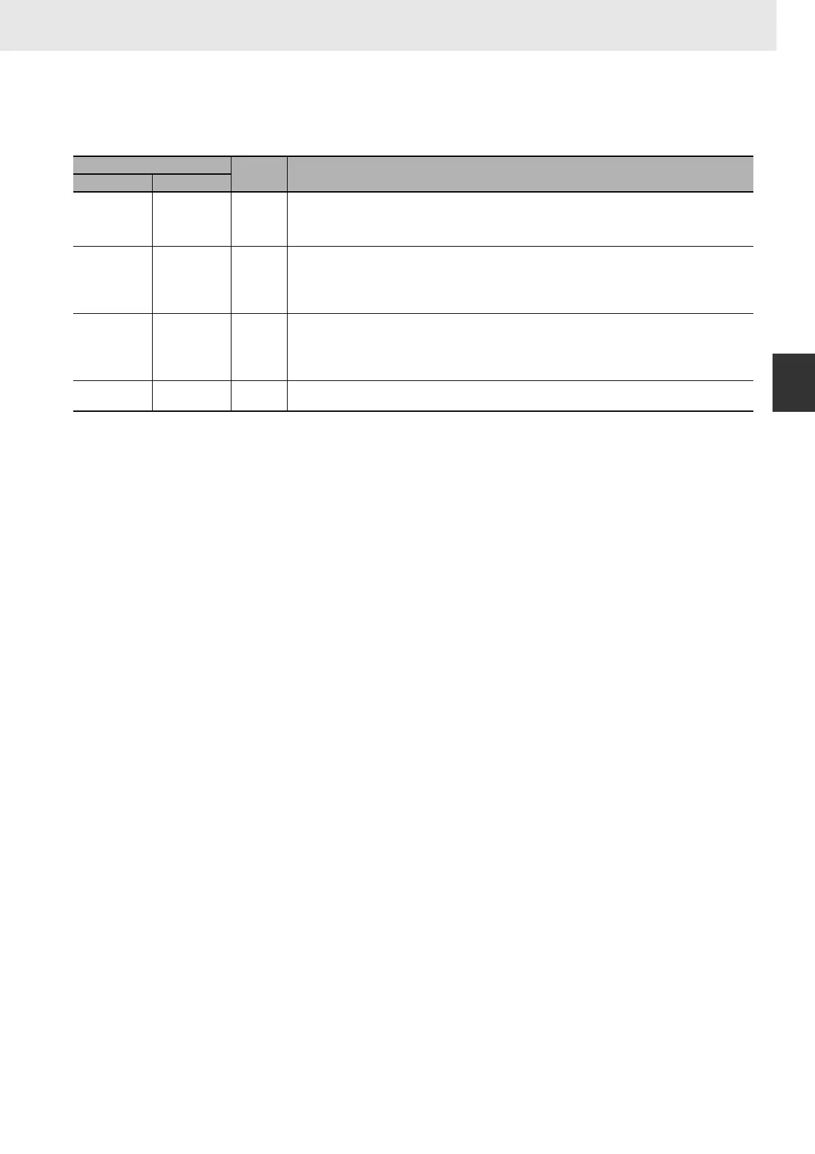
Word
Bit Function
Port 1 Port 2
n+8 n+18 04
Overrun Error Flag
1: The reception buffer contained more than 259 bytes of data before RXDU(255) was executed.
Note: Once this error flag goes ON, it can be turned OFF only by turning the power OFF and then ON again
or restarting the Board.
n+9 n+19 06
Reception Completed Flag
0: No data received or currently receiving data
1: Reception completed
0 → 1:The Board or Unit has received the specified number of bytes.
1 → 0:RXD(235) or RXDU(255) was executed to write the data from the buffer to a CPU Unit data area.
n+9 n+19 07
Reception Overflow Flag
0: The Board or Unit has not received more than the specified number of bytes.
1: The Board or Unit has received more than the specified number of bytes.
0 → 1:The Board or Unit received more data after data reception was completed.
1 → 0:RXD(235) or RXDU(255) was executed to write the data from the buffer to a CPU Unit data area.
n+10 n+20 00 to 15
Reception Counter
Indicates the number of bytes received in hexadecimal, between 0000 and 0100 hex (0 to 256 decimal).