3. Instructions
896
CS/CJ/NSJ Series Instructions Reference Manual (W474)
Related Auxiliary Area Words and Bits
Note The Settings Changing Flags for port 3 and port 4 are reserved for future use.
Function
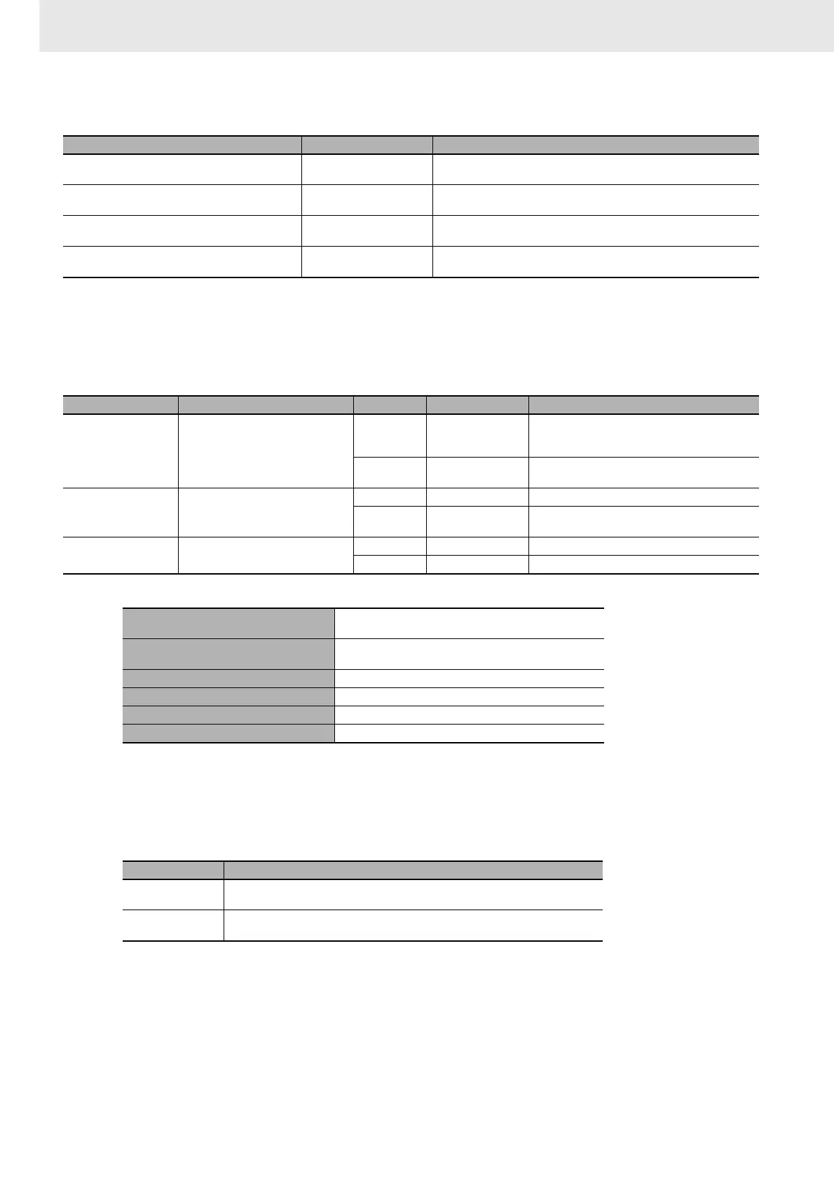
STUP(237) writes 10 words of data from S to S+9 to the communications setup area of the Unit with the
specified unit address, as shown in the following table. When the constant #0000 is designated to S, the
communications settings of the corresponding port will be set to default.
The following data is stored in the 10 words from S to S+9.
When STUP(237) is executed, the corresponding Port Parameters Changing Flag (A619.01, A619.02,
or A619 to A636) will turn ON. The flag will remain ON until changing the parameters has been
completed.
Note If the PLC is turned OFF and then ON again after STUP(237) has been used to change the communications
parameters, the new parameters will be retained or will revert to the previous parameters, depending on the
CPU Unit.
Name Address Contents
Peripheral Port Parameters Changing Flag A619.01 ON when the communications parameters are being changed for the
peripheral port.
RS-232C Port Parameters Changing Flag A619.02 ON when the communications parameters are being changed for the RS-
232C port.
Port Parameters Changing Flags for ports 1 to 4 on
Serial Communications Units 1 to 15.
A620 bit 01 to bit 04
to A635 bit 01 to bit 04
ON when the communications parameters are being changed for a port
on a Serial Communications Unit.
Port Parameters Changing Flags for ports 1 to 4 on
the Serial Communications Board (CS Series only)
A636.01 to A636.04 ON when the communications parameters are being changed for a port
on the Serial Communications Board.
Unit address Unit Port No. Serial port Serial port communications setup area
00 hex CPU Unit
1 hex
Peripheral Port Communications parameters for the peripheral
port in the PLC Setup (Cannot be specified for a
CJ2 CPU Unit.)
2 hex
RS-232C Port Communications parameters for the RS-232C port
in the PLC Setup
Unit No. + 10 hex Serial Communications Unit (CPU
Bus Unit)
1 hex Port 1 10 words starting from D30000 + 100 × Unit No.
2 hex
Port 2 10 words starting from D30000 + 100 × Unit No. +
10
E1 hex Serial Communications Board (Inner
Board) (CS Series only)
1 hex Port 1 10 words starting from D32000
2 hex Port 2 10 words starting from D32010
Peripheral port on CPU Unit
PLC Setup settings in Programming Console addresses
+144 to +153
RS-232C port built into CPU Unit
PLC Setup settings in Programming Console addresses
+160 to +169
Serial Communications Unit port 1 m to m+9 (m = D30000 × unit number)
Serial Communications Unit port 2 m+10 to m+19 (m = D30000 ¥ unit number)
Serial Communications Board port 1 D32000 to D32009
Serial Communications Board port 2 D32010 to D32019
CPU Unit Status of communications parameters
CJ2, CS1-H, CJ1-H,
CJ1M, or CS1D
If the PLC is turned OFF and then ON again, the communications parameters revert
to the settings that existed before they were changed with STUP(237).
CS1/CJ1 If the PLC is turned OFF and then ON again, the communications parameters set
with STUP(237) are retained.