945
3. Instructions
CS/CJ/NSJ Series Instructions Reference Manual (W474)
Network Instructions
3
CMND
Note 1 Refer to the operation manual for the specific network for the maximum data lengths for the command data and
response data. For any FINS command passing through multiple networks, the maximum data lengths for the com-
mand data and response data are determined by the network with the smallest maximum data lengths.
If response data longer than the number response data bytes is returned, the response data is not stored. If response
data shorter than the number of response data bytes is returned, the response data is received and the remaining
area remains unchanged.
2 The following two methods can be used to send a FINS command to a host computer through a serial port with the
host link host link while initiating communications from the PLC, or the serial gateway function (converted to Compo-
Way/F, Modbus-RTU, or Modbus-ASCII).
1) Set the destination unit address (bits 00 to 07 of C+3) to the unit address of the CPU Unit or Serial Communica-
tions Unit/Board and set the serial port number (bits 08 to 11 of C+2) to 1 for port 1 or 2 for port 2.
2) Set the source unit address directly into bits 00 to 07 of C+2. In this case, set the serial port number in bits 08 to 11
of C+1 to 0 for direct specification.
• Serial Communication Unit Ports
• Serial Communication Board Ports
Unit address
(C+2, bits 00 to 07)
Unit
Serial port number
(C+1, bits 08 to 11)
Serial port
00 hex CPU Unit 1 hex Built-in RS-232C port
2 hex Peripheral port
10 hex + unit number Serial Communications Unit
(CPU Bus Unit)
1 hex Port 1
2 hex Port 2
E1 hex Serial Communications Board
(Inner Board) (CS Series only)
1 hex Port 1
2 hex Port 2
Port Port’s unit address Example: Unit number = 1
Port 1 80 hex + 4 × unit number 80 + 4 × 1 = 84 hex (132 decimal)
Port 2 81 hex + 4 × unit number 81 + 4 × 1 = 85 hex (133 decimal)
Port Port’s unit address
Port 1 E4 hex (228 decimal)
Port 2 E5 hex (229 decimal)
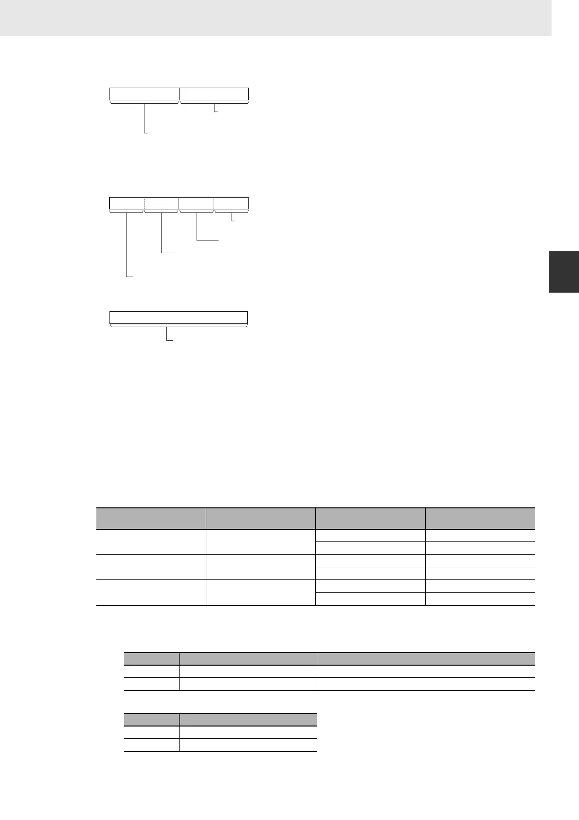
C+3
Destination unit address (See note 6)
#00 to FE hex
Destination node address (See note 5)
00 to maximum node address (hex)
(Depends on the network.
Example: In the case of Controller Link,
#00 to 20 hex (0 to 32))
#FF: Broadcast
8
15
07
C+4
Resend times
#0 to F (0 to 15)
#0 fixed
8
111215
0347
Logical port number
#0 to 7 (#F: automatic allocation)
Response needed / not needed (See note 7)
#0: Response needed
#8: Response not needed
C+5
0
15
Response Timeout
&1 to 65535 decimal (#0001 to FFFF hex)
0.1 to 6553.5 sec
#0000: 2s (default value)