3. Instructions
954
CS/CJ/NSJ Series Instructions Reference Manual (W474)
The serial port unit address are as follows:
• Serial Communications Units:
Port 1: 80 hex + 04 hex
× unit number
Port 2: 81 hex + 04 hex
× unit number
• Serial Communications Boards:
Port 1: E4 hex (228 decimal)
Port 2: E5 hex (229 decimal)
•CPU Unit
Peripheral port: FD hex (253 decimal)
RS-232C port: FC hex (252 decimal)
3 Set FF hex for broadcasting. Set 00 hex to sent to the local node. When specifying a serial port using a serial gate-
way (converting to Host Link FINS), set the destination node address to one higher than the Host Link unit number of
the destination PLC (1 to 32).
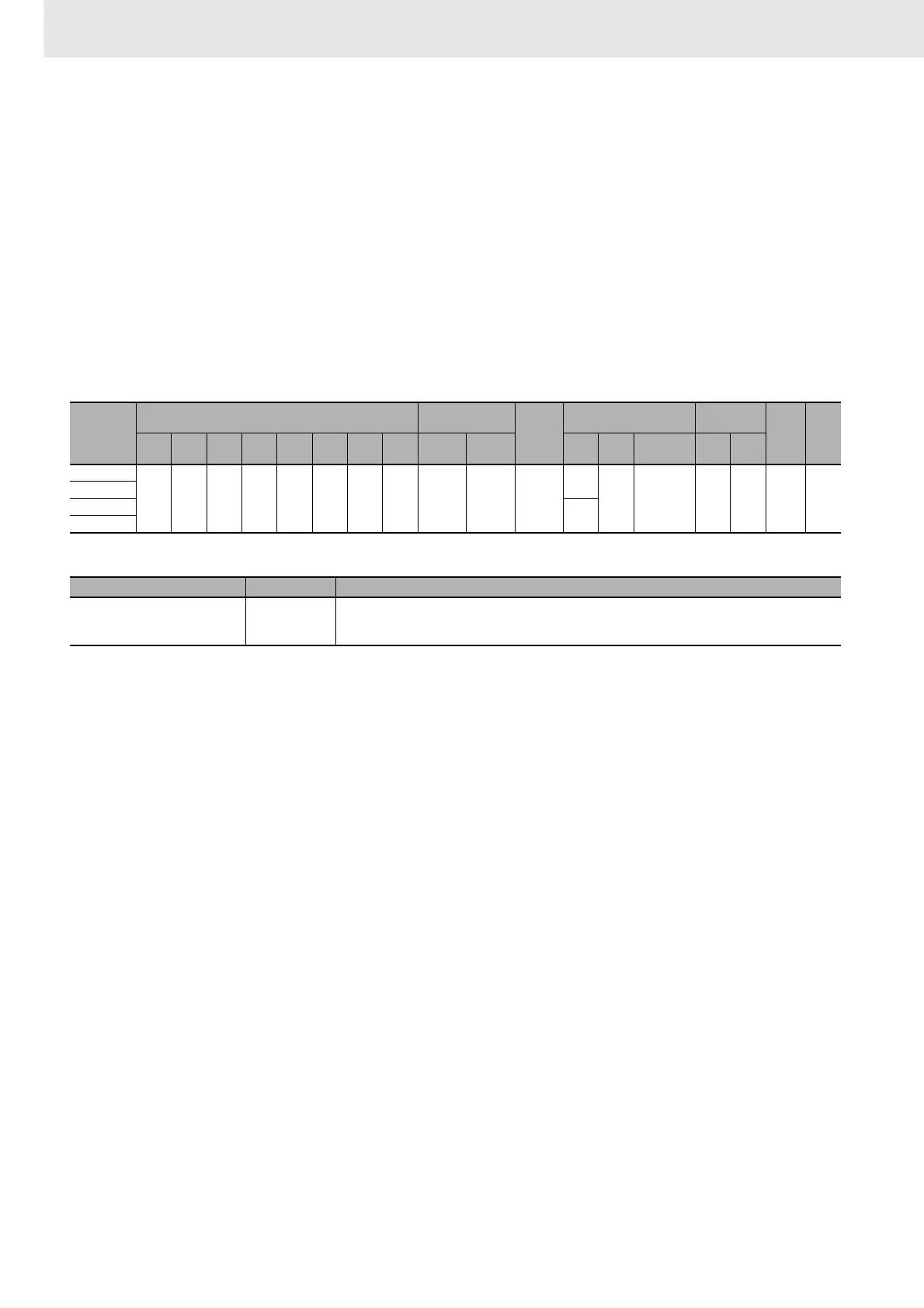
z Operand Specifications
Flags
Function
CMND2(493) transfers the specified number of bytes of FINS command data beginning at word S to the
device with the designated unit address through the PLC's CPU Bus or over a network. The response is
stored in memory beginning at word D.
CMND2(493) can be used to send an FINS command to the local CPU Unit as well.
This is mainly done to send FINS commands for file memory operations.
The File Memory Operation Flag (A343.13) will turn ON when any FINS command is sent to the local
CPU Unit (even for FINS commands not related to file memory). Always use A343.13 in an NC input
condition for CMND2(493) to ensure that only one FINS command is being executed for the CPU Unit
at the same time.
This means that command cannot be simultaneously sent to the local CPU Unit using both the
CMND(490) and CMND2(493) instructions.
When sending starts, the Execution Completed Flag in I is turned OFF. When a response is returned,
the results of the send is shown in the Error Flag in I. The communications response is written to I+1.
The Communications Port Enabled Flags (A202.00 to A202.07) and Communications Port Error Flags
(A219.00 to A219.07) used for the CMND(492) instruction are not used for CMND2(493), which uses
the operand I. The communications port completion code (previously stored in A203 to A210) is stored
in I+1.
Area
Word addresses
Indirect DM/EM
addresses
Con-
stants
Registers Flags
Pulse
bits
TR
bits
CIO WR HR AR T C DM EM
@DM
@EM
*DM
*EM
DR IR
Indirect
using IR
TK CF
S
OK OK OK OK OK OK OK OK OK OK ---
OK
--- OK --- --- --- ---
D
C
---
I
Name Label Operation
Error Flag P_ER • ON if the serial port number specified in C+1 is not between 0 and 4 hex.
• ON if there is no communications port available (i.e., if A211 = 0).
• OFF in all other cases.