284
Index Registers Section 6-2
Instructions That Directly Address Index Registers
Index registers can be directly addressed by the following instructions.
DOUBLE SIGNED BINARY ADD WITHOUT CARRY: +L(401), DOUBLE
SIGNED BINARY SUBTRACT WITHOUT CARRY: –L(411), DOUBLE
INCREMENT BINARY: ++L(591), and DOUBLE DECREMENT BINARY: – –
L(593)
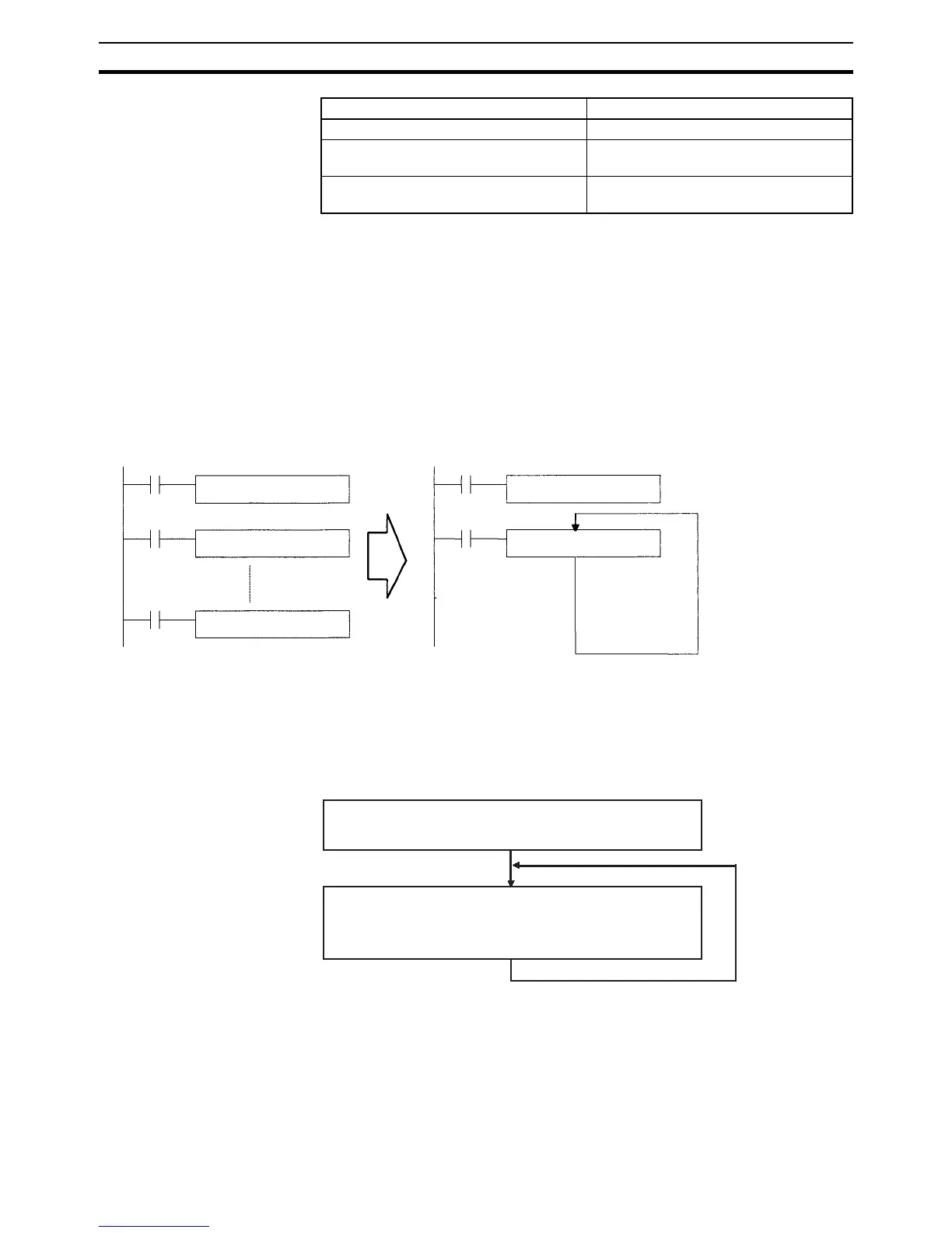
Example 1
The following example shows how an Index Register in a program loop can
replace a long series of instructions. In this case, instruction A is repeated n+1
times to perform some operation such as reading and comparing a table of
values.
Example 2
The data in D00000 to D00099 (augend data) is added to the data in D00100
to D00199 (addend data) and the addition results are output to D00200 to
D00299. The operands of a single addition instruction are specified by index
registers and the addition operations are performed by incrementing the index
registers and repeatedly executing the addition instruction.
Indirect addressing with DR offset DR@,IR@
Indirect addressing with auto-increment Increment by 1: ,IR@+
Increment by 2: ,IR@++
Indirect addressing with auto-decrement Decrement by 1: ,–IR@
Decrement by 2: ,– –IR@
Variation Syntax
Instruction A m
Instruction A m+1
Instruction A m+n
MOVR(560) m IR0
Instruction A ,IR0+
Stores the PLC memory
address of m in IR0.
Repeats the process
in a loop such as
FOR-NEXT.
MOVR(560) sets the PLC memory addresses of D00000, D00100, and D00200
in index registers IR0, IR1, and IR2.
The augend data (indirectly addressed by IR0+) is added to the addend data
(indirectly addressed by IR1+) with the SIGNED BINARY ADD WITHOUT
CARRY instruction (+(400)) and the result is output to the word indirectly
addressed by IR2+. Index registers IR0, IR1, and IR2 are automatically
incremented after being referenced in the +(400) instruction.
Repeated 100 times.