6 Interrupts
6-10
CJ2M CPU Unit Pulse I/O Module User’s Manual
* Terminals numbers on the XW2D-@@G@ Connector-Terminal Block Conversion Unit.
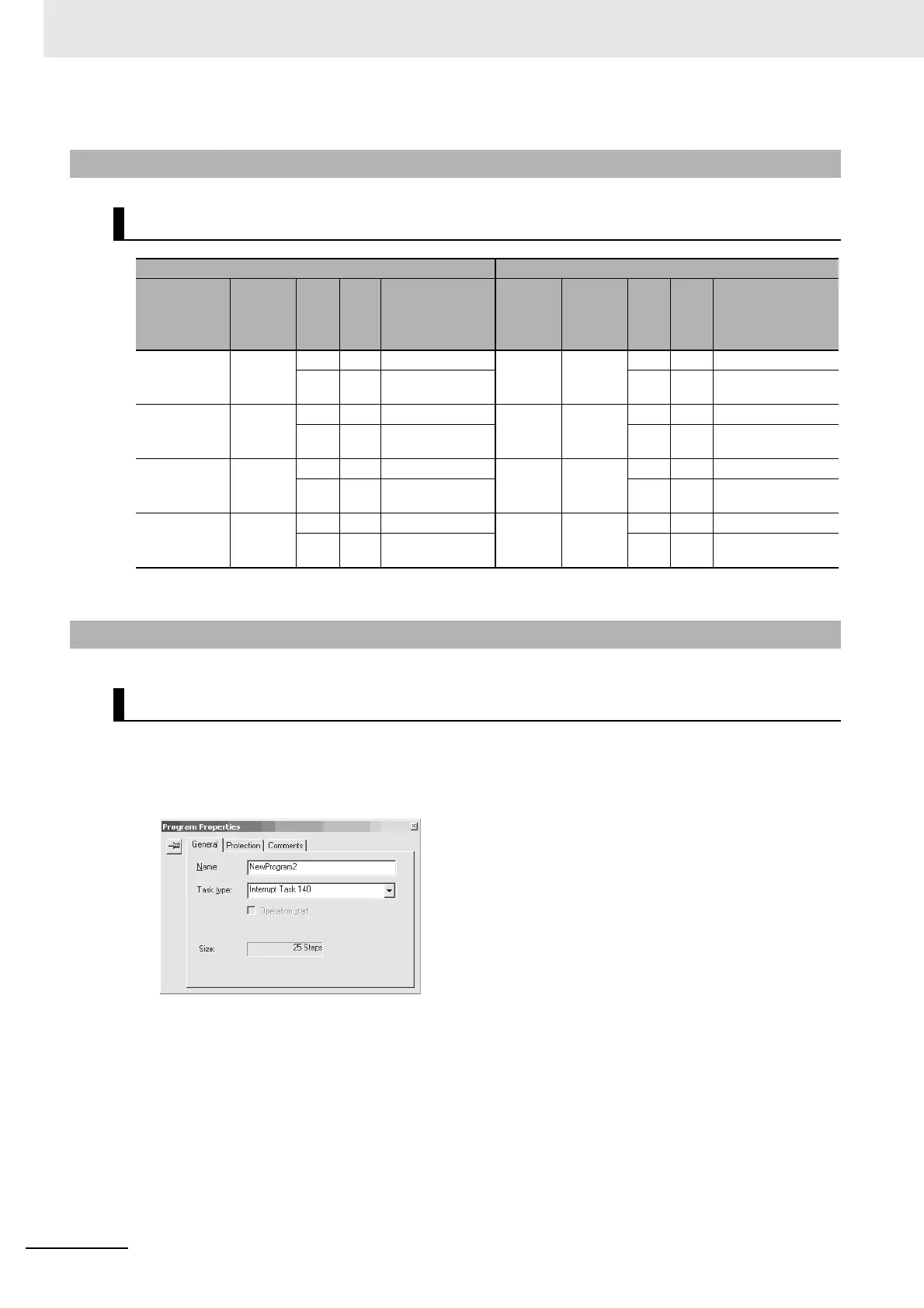
Create ladder programs for interrupt tasks 140 to 147, which are executed for the corresponding
interrupt inputs. Right-click the program set as the interrupt task in the CX-Programmer and select
Properties. Select interrupt tasks 140 to 147 in the Task Type Field of the Program Properties Dia-
log Box.
6-2-5 Wiring
Connector Pin Assignments
Pulse I/O Module No. 0 (on the right) Pulse I/O Module No. 1 (on the left)
Input type
and number
Termi-
nal
symbol
Pin (*) Description
Input
type
and
number
Termi-
nal
symbol
Pin (*) Description
Interrupt
input 0
IN00 1 A1 24-VDC input Inter-
rupt
input 4
IN10 1 A1 24-VDC input
5A30 V 5A30 V
Interrupt
input 1
IN01 2 B1 24-VDC input Inter-
rupt
input 5
IN11 2 B1 24-VDC input
6B30 V 6B30 V
Interrupt
input 2
IN02 7 A4 24-VDC input Inter-
rupt
input 6
IN12 7 A4 24-VDC input
11 A6 0 V 11 A6 0 V
Interrupt
input 3
IN03 8 B4 24-VDC input Inter-
rupt
input 7
IN13 8 B4 24-VDC input
12 B6 0 V 12 B6 0 V
6-2-6 Creating Ladder Programs
Writing the Interrupt Task's Ladder Program