2-9
2 I/O Application Procedures and Function Allocations
CJ2M CPU Unit Pulse I/O Module User’s Manual
2-3 PLC Setup
2
2-3-1 Normal Input Operation Setting
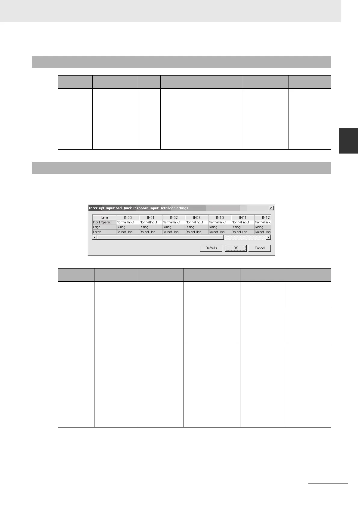
The following dialog box will be displayed if the Set Button in the Interrupt Inputs and Quick-response
Inputs Area of the I/O Module Tab Page in the PLC Setting Dialog Box. Items that cannot be set will be
grayed out. The items that are grayed out can be set if the required Input Operation is set.
* Only specific pairs of interrupt inputs and pulse outputs can be used together when using interrupt
inputs with the INTERRUPT FEEDING (IFEED(892))) instruction. For details, refer to 8-4-4 INTER-
RUPT FEEDING Instruction: IFEED(892).
2-3-1 Normal Input Operation Setting
Parameter Setting Default Description
Related Auxiliary
Area words and bits
Update timing in
CPU Unit
Input Time
Constant
• Default (8 ms)
•No filter
• 0.5 ms
•1 ms
•2 ms
•4 ms
•8 ms
•16 ms
•32 ms
Default
(8 ms)
Set the input time constant for normal
inputs IN00 to IN19.
Note The input constant is ignored for
input terminals that are set for inter-
rupt inputs, quick-response inputs,
and high-speed counters.
--- Refreshed when
power is turned ON.
2-3-2 Interrupt Input and Quick-response Input Detailed Settings
Parameter Setting Default Description
Related Auxiliary
Area words and bits
Update timing in
CPU Unit
Input Operation • Normal Input
• Quick-response
Input
• Interrupt Input
Normal Input Set the function of the inter-
nal input.*
--- Refreshed when
power is turned ON.
Edge • Rising Edge
• Falling Edge
Rising Edge This setting is valid only
when the input is set to
Interrupt Input.
Set whether an interrupt will
occur when the input turns
ON or OFF.
--- Refreshed when
operation is started.
Latch • Do not Use
• Pulse Output 0
• Pulse Output 1
• Pulse Output 2
• Pulse Output 3
• High-speed
Counter 0
• High-speed
Counter 1
• High-speed
Counter 2
• High-speed
Counter 3
Do not Use This setting is valid only
when the input is set to
Interrupt Input.
Select the item to latch
when using the software
latch for the input for a
pulse output/high-speed
counter.
Latched PV: A10144
to A10159
Refreshed when
power is turned ON.