9 PWM Outputs
9-4
CJ2M CPU Unit Pulse I/O Module User’s Manual
* The duty ratio accuracy declines significantly at high frequencies because of limitations in the output circuit at
high frequencies.
*1 Terminals numbers on the XW2D-@@G@ Connector-Terminal Block Conversion Unit.
*2 If an origin search in operation mode 1 or 2 is used for an output port 0 to 3, an instruction error will occur.
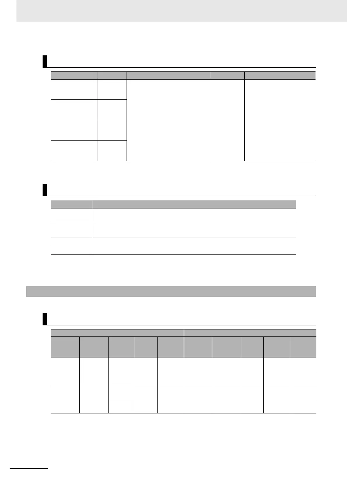
Related Auxiliary Area Bits
Name Bit Function Read/Write Refresh timing
PWM Output 0
Output In-
progress Flag
A283.00 ON when pulses are being output
from PWM output 0 to 3.
OFF: Stopped, ON: Outputting
Read • Cleared when power is
turned ON.
• Cleared when operation is
started or stopped.
• Refreshed when start-
ing/stopping pulse output.
PWM Output 1
Output In-
progress Flag
A283.08
PWM Output 2
Output In-
progress Flag
A329.00
PWM Output 3
Output In-
progress Flag
A329.08
Specifications
Item Specifications
Duty ratio 0.0% to 100.0% in 0.1% increments
(Duty ratio accuracy is +5%/-5% at 1 kHz.)
Frequency 0.1 Hz to 6,553.5 Hz (Set in 0.1-Hz increments.)*
1 Hz to 32,800 Hz (Set in 1-Hz increments.)*
Output mode Continuous Mode
Instruction PWM(891) instruction
9-1-3 Wiring
Connector Pin Assignments
Pulse I/O Module No. 0 (on the right) Pulse I/O Module No. 1 (on the left)
Output
type and
number
Terminal
symbol
Pin (*1)
Descrip-
tion
Output
type and
number
Terminal
symbol
(*1) Pin Pin
PWM out-
put 0
OUT04 35 A18 PWM
output
PWM out-
put 2
OUT14 A18 35 PWM
output
39 or 40 A20 or
B20
Output
COM
A20 or
B20
39 or 40 Output
COM
PWM out-
put 1
*2
OUT05 36 B18 PWM
output
PWM out-
put 3
*2
OUT15 B18 36 PWM
output
39 or 40 A20 or
B20
Output
COM
A20 or
B20
39 or 40 Output
COM