5 Quick-response Inputs
5-6
CJ2M CPU Unit Pulse I/O Module User’s Manual
5-3 Wiring
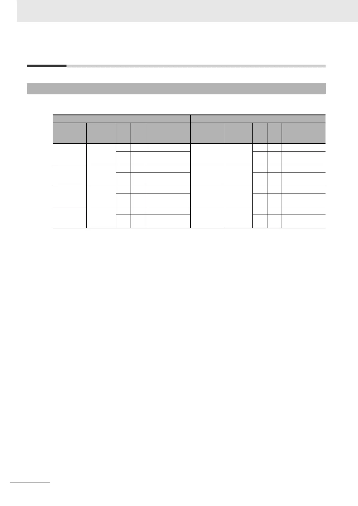
The following terminals can be used for quick-response inputs.
* Terminals numbers on the XW2D-@@G@ Connector-Terminal Block Conversion Unit.
5-3-1 Connector Pin Assignments
Pulse I/O Module No. 0 (on the right) Pulse I/O Module No. 1 (on the left)
Input type
and num-
ber
Terminal
symbol
Pin (*) Description
Input type
and num-
ber
Terminal
symbol
Pin (*) Description
Quick-
response
input 0
IN00 1 A1 24-VDC input Quick-
response
input 4
IN10 1 A1 24-VDC input
5A30 V 5A30 V
Quick-
response
input 1
IN01 2 B1 24-VDC input Quick-
response
input 5
IN11 2 B1 24-VDC input
6B30 V 6B30 V
Quick-
response
input 2
IN02 7 A4 24-VDC input Quick-
response
input 6
IN12 7 A4 24-VDC input
11 A6 0 V 11 A6 0 V
Quick-
response
input 3
IN03 8 B4 24-VDC input Quick-
response
input 7
IN13 8 B4 24-VDC input
12 B6 0 V 12 B6 0 V