7 High-speed Counters
7-12
CJ2M CPU Unit Pulse I/O Module User’s Manual
Encoders with Line Driver Outputs (Conforming to AM26LS31)
7-1-6 Creating Ladder Programs
Execution Program Reference
Generating interrupts for the
high-speed counter PV (num-
ber of pulses) and perform
high-speed processing.
Specify interrupt tasks with
CTBL(882) instructions.
7-3 High-speed
Counter Interrupts
Reading the high-speed
counter PV (number of
pulses).
Read the high-speed counter PV from
the Auxiliary Area or using the
PRV(881) instruction and convert it to
position or length data using instruc-
tions or measure the length using
comparison instructions such as =, <,
and >.
7-2-4 Reading the
Present Value
Reading the high-speed
counter frequency (speed).
Execute a PRV(881) instruction. 7-2-5 Frequency
Measurement
Reading the rotational speed
or total number of pulses from
the high-speed counter input
Execute a PRV2(883) instruction. 7-2-6 Measuring the
Rotational Speed or
Total Rotations
Changing or reading the PV of
the high-speed counter when
an interrupt input occurs
Use the software latch to write the PV
of the high-speed counter just before
the interrupt task is executed to the
Auxiliary Area.
Using Software
Latches on page 6-8
Reading the direction of the
high-speed counter
Read the high-speed counter direction
from the Auxiliary Area or by execut-
ing the PRV(881) instruction to read
status.
7-2-7 Reading the
Count Direction
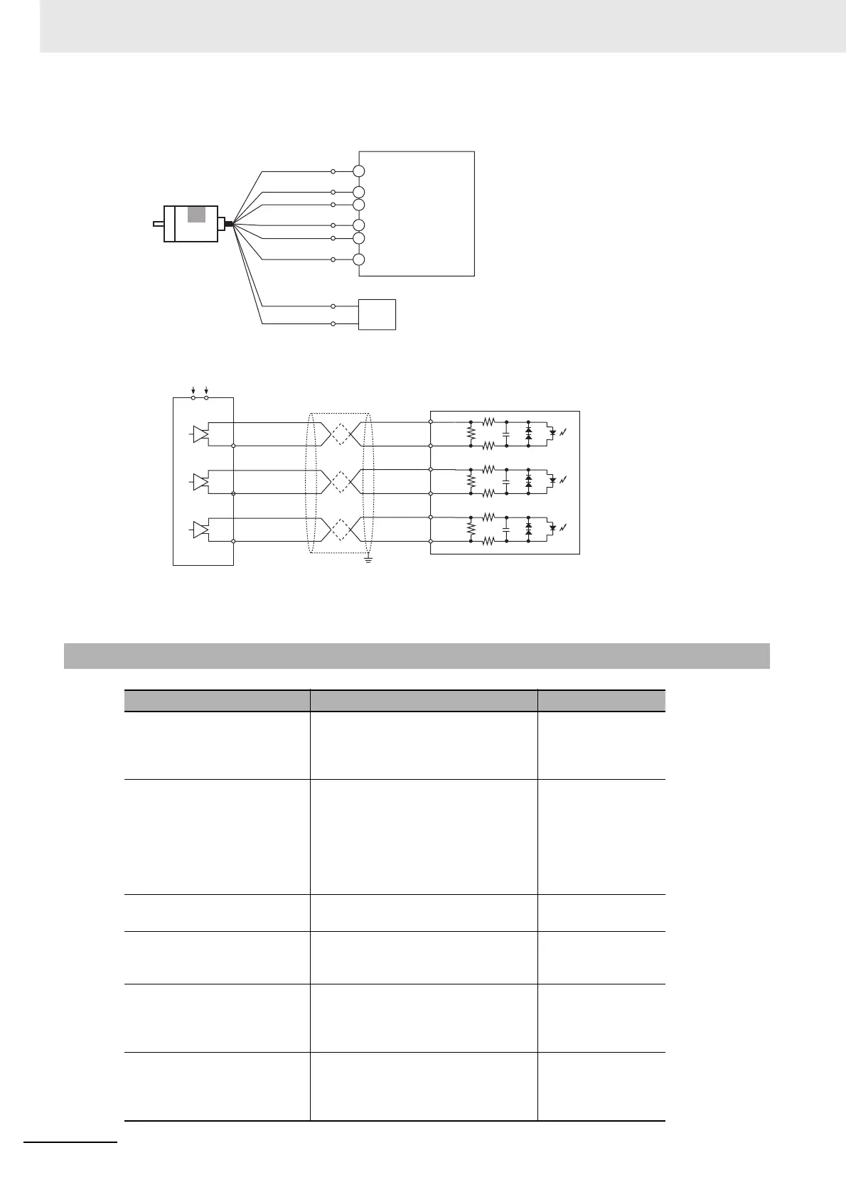
Pulse I/O Module
A-
Black
(striped)
B-
White
(striped)
Z
-
Orange
(striped)
Black
White
Orange
5 VDC
Brown
0 V
Blue
5-VDC power supply
+5 V
0 V
Encoder
Example:
E6B2-CWZ1X
Line driver outputs
Differential Phase Input Mode
29
(High-speed counter 0: Phase-A load − )
29
27
30
28
12
10
Encoder
Power supply
Shielded twisted-pair cable
(Do not use the same I/O power supply as other equipment.)
A-
B-
Z-
A+
B+
Z+
Pulse I/O Module
27
(High-speed counter 0: Phase-A load +)
28
(High-speed counter 0: Phase-B load +)
30
(High-speed counter 0: Phase-B load − )
10
(High-speed counter 0: Phase-Z load +)
12
(High-speed counter 0: Phase-Z load − )
A+
B+
Z+
 Loading...


