6 Interrupts
6-12
CJ2M CPU Unit Pulse I/O Module User’s Manual
(2) Enabling Interrupt Inputs
Example
The present value of an interrupt input counter can be read in the following two ways.
Pulse I/O
Module
No.
Terminal
symbol
Correspond-
ing bit
address
Function
Interrupt
task number
Operand N Operand C
Interrupt
identifier
Specifying to
detect ON or OFF
0 (on the
right)
IN00 CIO 2960.00 Interrupt input 0 140 100 #0000: Enable
interrupt (Direct
Mode)
#0001: Disable
interrupt
#0002: Enable
interrupt (Counter
Mode, decrement)
#0003: Enable
interrupt (Counter
Mode, increment)
IN01 CIO 2960.01 Interrupt input 1 141 101
IN02 CIO 2960.02 Interrupt input 2 142 102
IN03 CIO 2960.03 Interrupt input 3 143 103
1 (on the
left)
IN10 CIO 2962.00 Interrupt input 4 144 104
IN11 CIO 2962.01 Interrupt input 5 145 105
IN12 CIO 2962.02 Interrupt input 6 146 106
IN13 CIO 2962.03 Interrupt input 7 147 107
Reading the PV of an Interrupt Input Counter in Counter Mode
• Reading the PV Refreshed at the I/O Refresh
Timing or When the Interrupt Task Is Started
→ Read from the Auxiliary Area. (Refer to Related
Parameters in the Auxiliary Area
on page 6-13.)
• Value updated when a ladder program is exe-
cuted
→ Read PV by executing a PRV(881) instruction.
MSKS
112
#0000
END
END
MSKS
102
#0000
Interrupt task number 142
Cyclic task
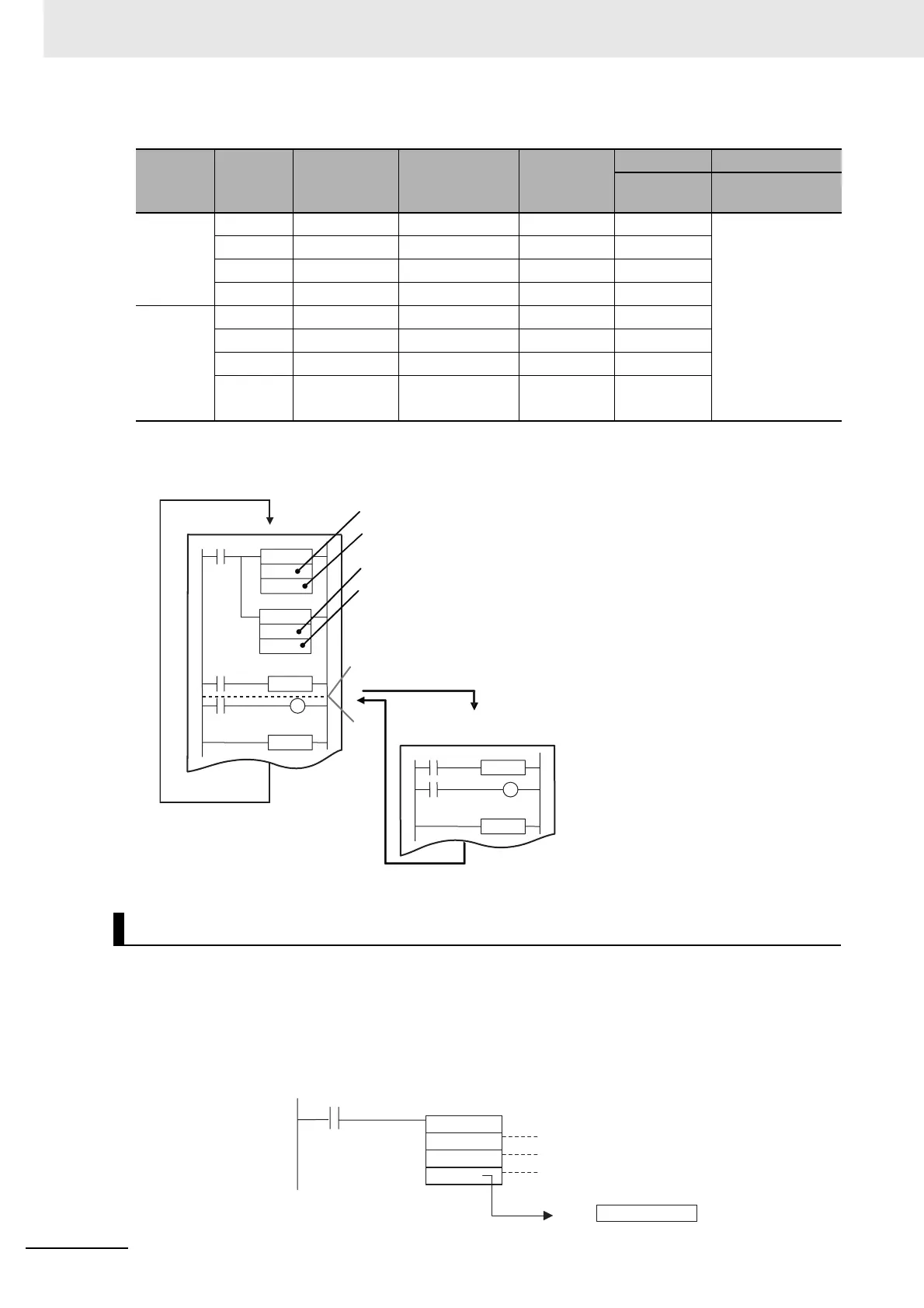
(1) Specify detecting ON or OFF input signals.
For interrupt input 2, specify 112.
Specifies detecting ON signals.
(2) Enabling interrupts.
For interrupt input 2, specify 102.
Enables interrupt in Direct Mode.
(3) Input received at IN02.
(4) Starting the interrupt task
#0100
#0000
D100
C: Control Data (to read PV)
P: Port specifier, Example: Interrupt input 0
D: First Destination Word
D100
@PRV
15
0
PV
Counter PV that was read
Execution condition