114
Setting up a network
Section 6-2
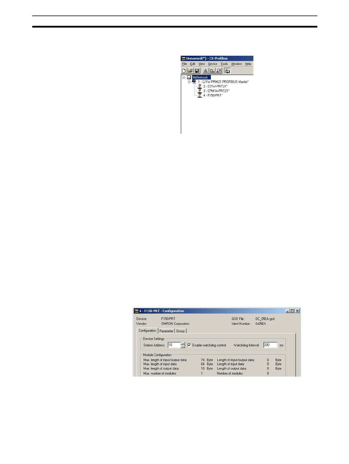
Example After completing the (example) network, the Network View contains the follow-
ing network (see figure below).
Note the that the slave DTMs all have the automatically assigned network
addresses, displayed to the left of the device name.
6-2-2 Changing Station Addresses
In order to achieve communication between the Master Unit and its allocated
slave devices, the latter must have the same physical network address as set
in the configuration. usually, the network address on the actual slave devices
are set through dip-switches, and this setting may differ from the address,
which was automatically assigned to the slave DTM.
Example For the example, it is assumed that the F150-PRT Vision system, has an
actual network address of 10, instead of 4, which was automatically assigned.
In order to change the network address of the F150-PRT, perform the proce-
dure outlined below.
1,2,3...
1. Open the Configuration User Interface for the F150-PRT, by selecting the
F150-PRT in the Network View, and double-clicking the left mouse button.
2. Select the Station Address field at the top of the Configuration tab (see fig-
ure below) and change the value to 10.
3. Select the OK or Apply button at the bottom of the window. The OK button
will close the DTM Configuration User Interface.
Note If, when pressing the Apply or OK button, no I/O modules have been selected
as yet, a warning message will be displayed. The I/O modules can be
selected later. Pressing the OK button with the warning, will apply the
changed station address.