122
Configuring the Master
Section 6-4
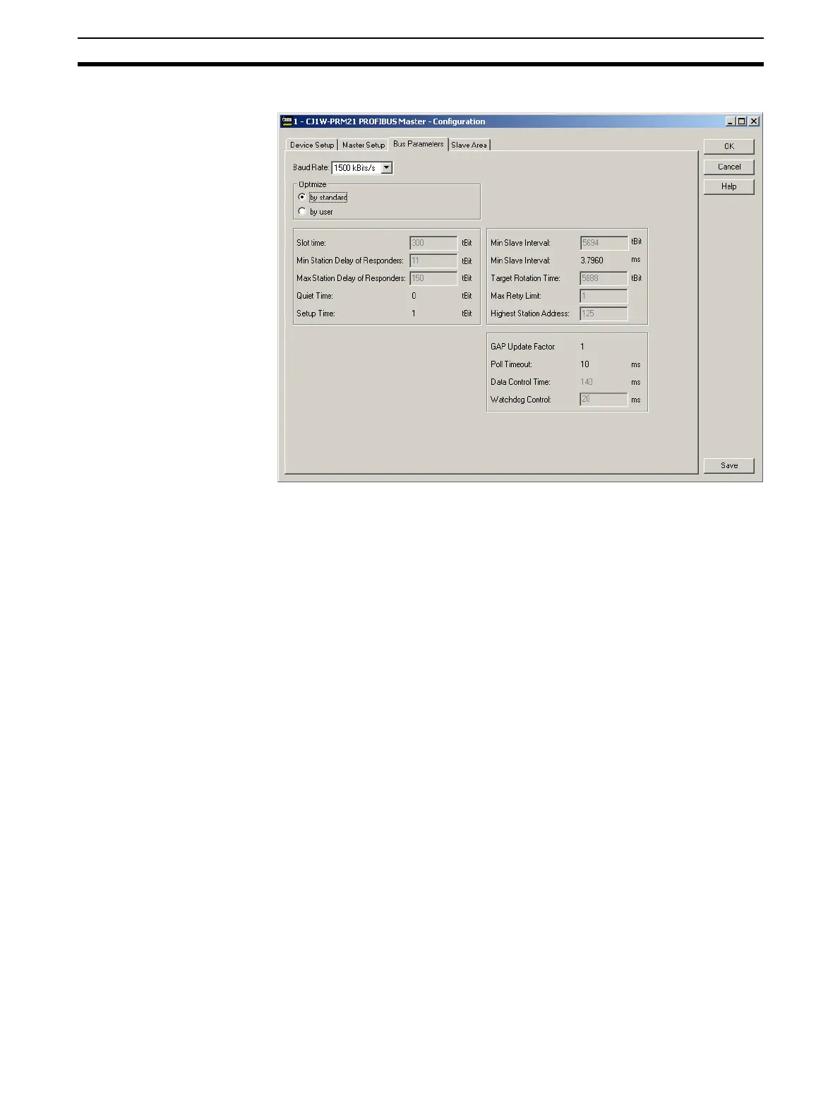
Example The Bus Parameter tab as used in the example is shown below.
The baud rate has been set to 1500 kBit/s. Given the amount of slaves and
the amount of I/O data, this results in a poll cycle time of approximately 3.8 ms
(Min Slave Interval).
Example After making the changes, select the Save button in the lower right corner of
the User Interface to accept the changes. Next select the Slave Area tab to
display the I/O Mapping.
6-4-3 Defining and Changing I/O Mapping
The I/O data of all slaves can be mapped on to the PLC Memory Areas.
through two Output Ares and two Input Areas. The Output data can be distrib-
uted over two Output Areas, each of which can be mapped on to PLC Mem-
ory. Similarly, the Input data can be distributed over two Input Areas, each of
which can be mapped on to PLC Memory.
Example The figure below shows the Master DTM’s Slave Area tab for the example net-
work.