123
Configuring the Master
Section 6-4
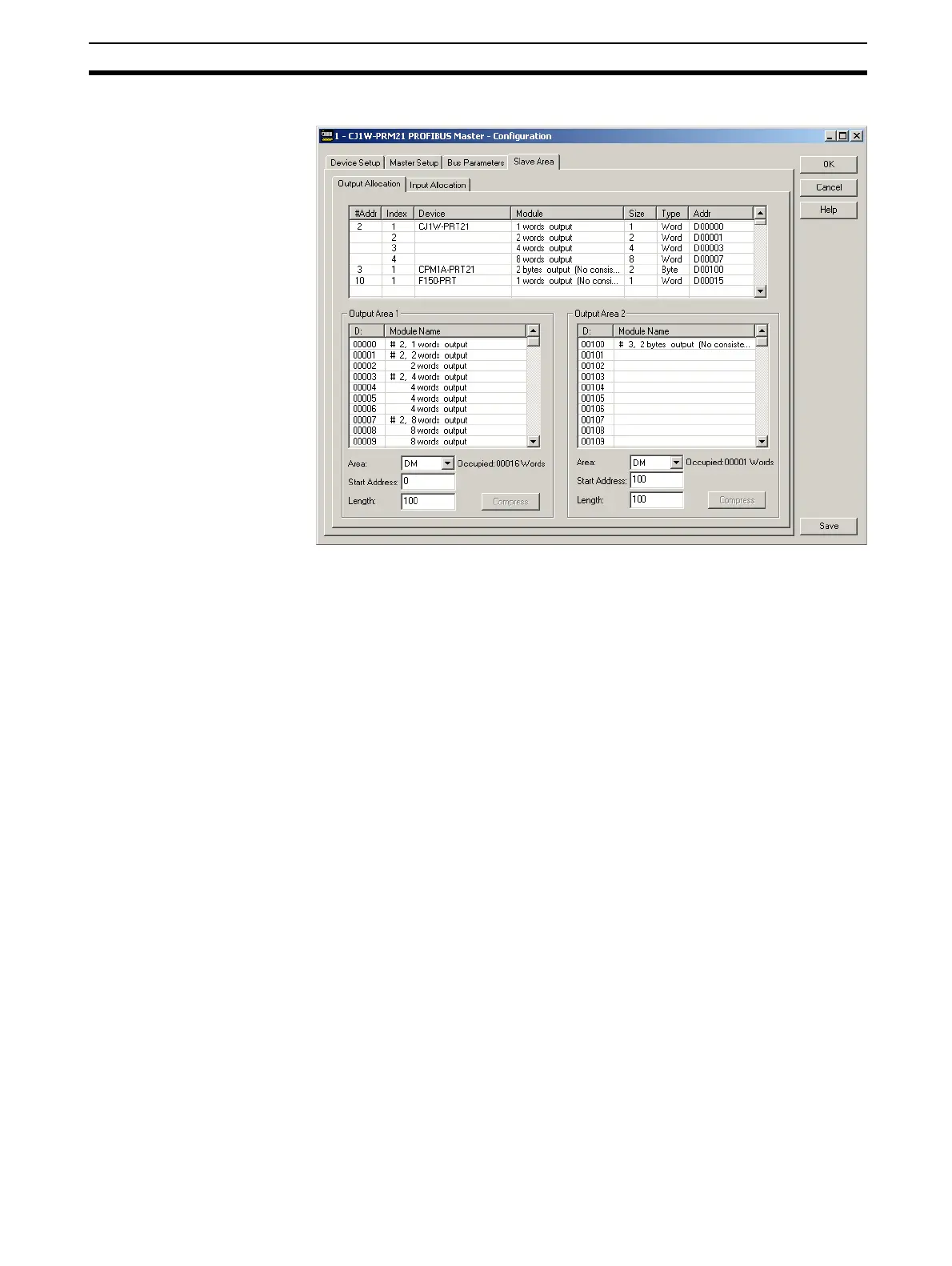
By default all Output data is mapped on to Output Area 1, and all Input data is
mapped on to Input Area 1. Each of these Areas can independently be
mapped on to PLC Memory.
Changing the mapping can be achieved using drag & drop. The module which
is mapped to Area 1 and which must be mapped to area 2, can be copied
there by dragging it from the collective list on top to Area 2.
6-4-4 Configuring CX-Server
Configuring
communication
The PROFIBUS-DP Master DTM uses CX-Server to connect to the Unit for
both downloading a configuration as well as monitoring the master Unit. In
order to setup the communication to the Unit, perform the following procedure.
1,2,3...
1. Open the Master DTM Configuration Interface, Device Setup tab.
2. Make sure that the Unit Number has been set to the unit number set on the
PROFIBUS-DP Master Unit, through the rotary switch on the front.
3. Select the Configure button to start CX-Server.