27
Unit Components
Section 2-1
DM Area Allocations
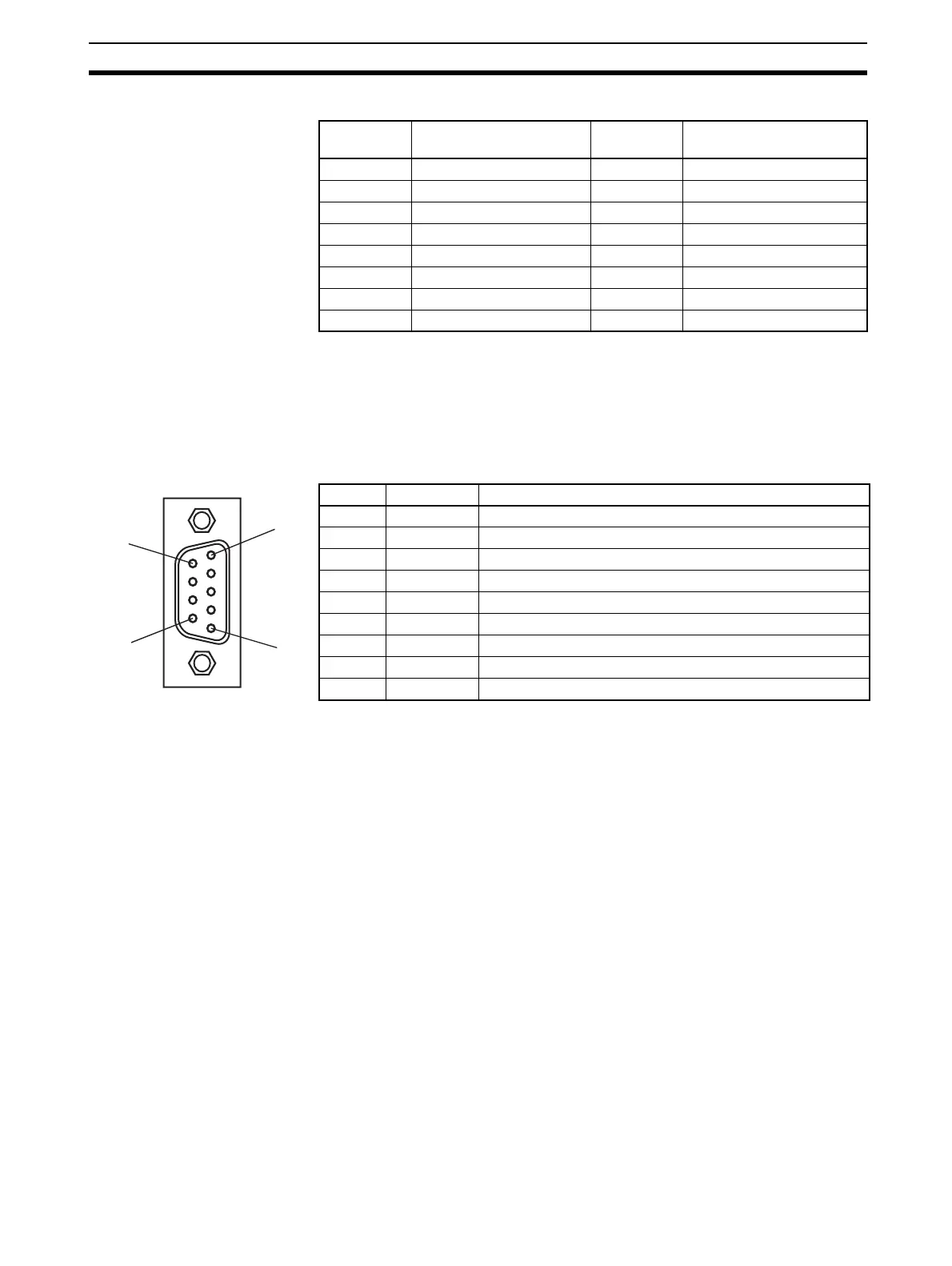
2-1-4 PROFIBUS Connector
The PROFIBUS connector on the font of the Unit is a 9-pin female sub-D con-
nector, as recommended by the PROFIBUS standard EN 50170.
The signal RTS (TTL signal) is for the direction control of repeaters, which do
not have a self-controlling capability.
The signals DGND and VP are used to power the bus terminator located in
the cable connector.
Note The orientation of the sub-D connector allows the use of PROFIBUS connec-
tors with a 90° angle cable outlet, e.g ERNI, Delconec and Phoenix.
Note The 9-pin sub-D connector uses #4/40 UNC thread, for mechanical fixation of
the cable connector. Make sure that if non-standard PROFIBUS connectors
are used, the corresponding thread is used on the cable connector.
Unit No.
(decimal)
Allocated words Unit No.
(decimal)
Allocated words
0 (0) D30000 to D30099 8 (8) D30800 to D30899
1 (1) D30100 to D30199 9 (9) D30900 to D30999
2 (2) D30200 to D30299 A (10) D31000 to D31099
3 (3) D30300 to D30399 B (11) D31100 to D31199
4 (4) D30400 to D30499 C (12) D31200 to D31299
5 (5) D30500 to D30599 D (13) D31300 to D31399
6 (6) D30600 to D30699 E (14) D31400 to D31499
7 (7) D30700 to D30799 F (15) D31500 to D31599
Pin No. Signal Description
1 Shield Shield/protective ground
2--
3 RxD/TxD-P Receive/Transmit data - plus (B wire)
4 RTS Control signal for repeaters (direction control) (TTL)
5 DGND Data ground (reference potential for VP)
6 VP Supply voltage of the terminator resistance (5 Vdc)
7--
8 RxD/TxD-N Receive/Transmit data - minus (A wire)
9--
5
9
1
6