25
Unit Components
Section 2-1
2-1-2 Indicators
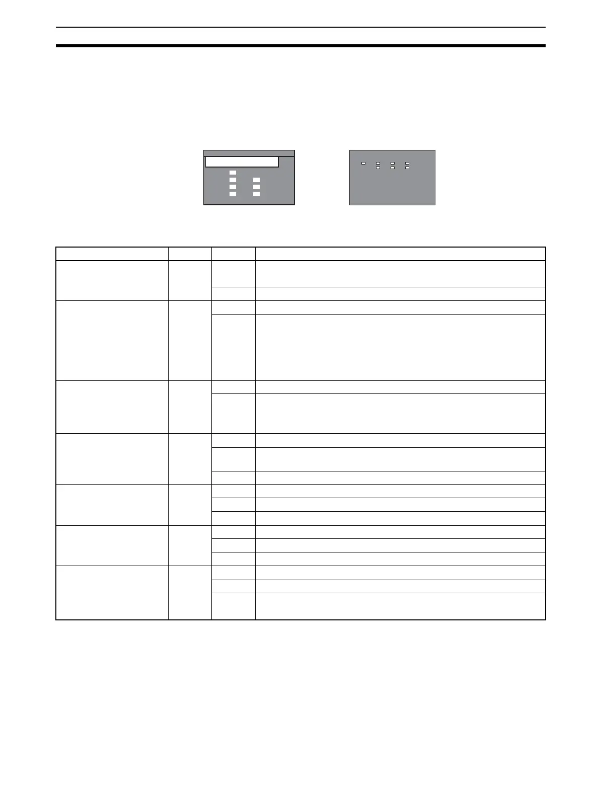
The PROFIBUS-DP Master Units are each fitted with seven LEDs to indicate
the operational mode and status of the Unit and the PROFIBUS network
Indicator specifications
Note Unless otherwise specified, the frequency of a flashing LED is 1 Hz (50% duty
cycle).
CJ1W-PRM21CS1W-PRM21
PRM21
CS
RUN
ERC
BST
BF
ERH
PRM
COMM
ERC
RUN
BF
PRM21
COMM
BST
ERH
PRM
Indicator Color Status Meaning
RUN Green Not lit • Startup test failed, Unit not operational.
• Operation stopped, due to a fatal error.
Lit Initialization successful, Unit is in normal operation.
ERC
(PROFIBUS-DP Master
Unit Error)
Red Not lit Unit is in normal operation.
Lit One of the following errors occurred:
• Startup error.
• Non-volatile memory error (checksum failed, write-verify failed).
• Invalid PROFIBUS parameter configuration setting.
• Fatal error in program execution.
ERH
(PLC Error)
Red Not lit PLC CPU in normal operation.
Lit One of the following errors occurred:
• PLC CPU Bus error.
• Cyclic Refresh Monitor Time-out.
PRM
(Parameter database)
Green Not lit PROFIBUS Parameter configuration is not available or incorrect.
Flashing PROFIBUS Parameter configuration is being transferred to the Unit and
is not yet available.
Lit PROFIBUS Parameter configuration is correct, and operational.
BST
(Bus status)
Green Not lit The PROFIBUS-DP Master Unit is in OFFLINE or STOP mode.
Flashing The PROFIBUS-DP Master Unit is in CLEAR mode.
Lit The PROFIBUS-DP Master Unit is in OPERATE mode.
COMM
(I/O Data communication)
Green Not lit No PROFIBUS data exchange with any of the allocated slaves.
Flashing Fatal error occurred (ERC LED is ON). Unit initialization failed.
Lit PROFIBUS data exchange ongoing with at least one allocated slave.
BF
(Bus Fail)
Red Not lit No PROFIBUS communication errors occurred.
Flashing At least one allocated slave is not in data exchange with the Unit.
Lit An error occurred in the PROFIBUS interface of the Unit
(see section
7-2 Troubleshooting Using LED Indicators
).