147
Appendix A
Bus Parameters
A-1 Bus Parameters
The PROFIBUS Bus Parameters define both the baud rate and the bus timing settings, necessary to perform
the exchange of messages over PROFIBUS. The Bus Parameters settings must be determined for each and
every Master station on the bus, and usually depend on
• the number of I/O data bytes per slave station,
• the number of slave stations connected to the master,
• the number of other masters on the bus.
The Bus Parameter settings consist for one part of a number of settings, which are directly entered in to the
PROFIBUS interface hardware registers. These settings implement the necessary timing to enable the transfer
of a single message between the PROFIBUS-DP Master Unit and a slave station. The other part of the Bus
Parameters must be calculated. These parameters implement the overall cyclic timing as well as the watchdog
timing s to monitor the communication.
The calculation is performed by the PROFIBUS-DP Master Unit DTM. The software implements a formula to
calculate the settings which will be downloaded to the PROFIBUS-DP Master unit. Most of the parameters
have baud rate dependent default values. Some of the parameters can be tuned by the user. However, this is
not recommended, since the communication may not function correctly, due to incorrect settings or too small
timing margins.
This appendix defines the parameters which are shown by the PROFIBUS-DP Master Unit DTM, and provides
the formula used for the timing calculations.
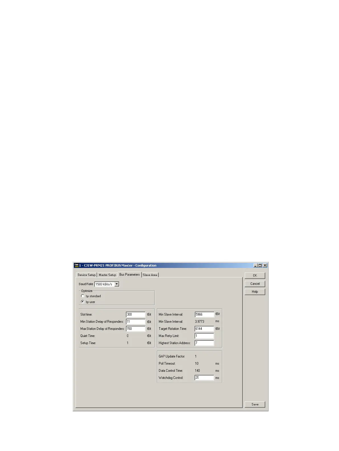
A-2 Bus Parameter definitions
The figure below shows the PROFIBUS-DP Master Unit DTM, Bus Parameter tab, in which the bus parameter
settings can be made.