20
Basic Operating Procedure
Section 1-5
1-5 Basic Operating Procedure
1-5-1 Overview
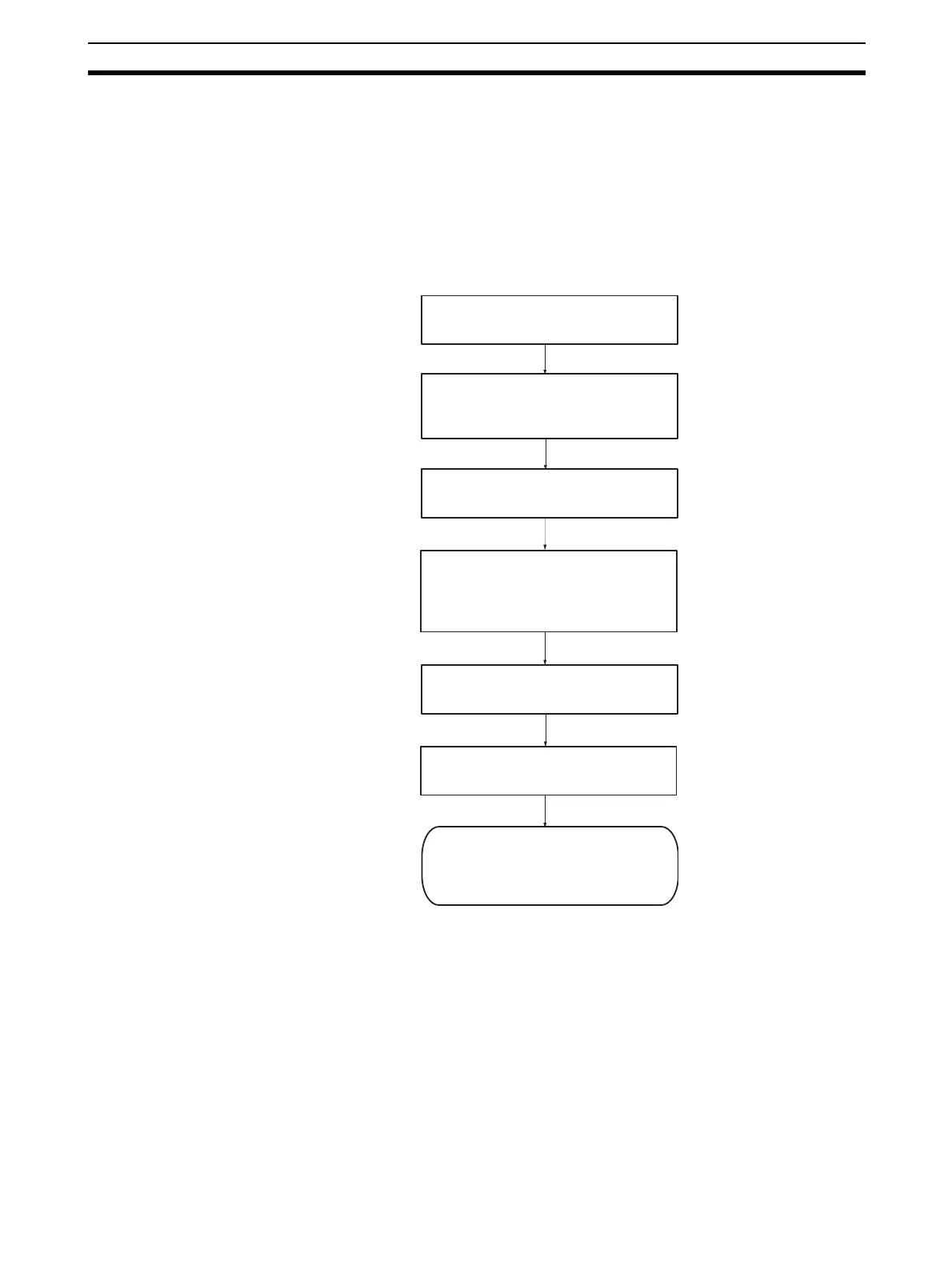
The following diagram provides an overview of the installation procedures.
For experienced installation engineers, this may provide sufficient informa-
tion. For others, cross-references are made to various sections of this manual
where more explicit information is given. When reading this manual online, the
flow chart entries provide links to the sections containing detailed information.
(1)
(2)
(3)
Select a unique Identity number (0 - F)
for the Unit with the rotary switch on the
front of the Unit.
Connect the PROFIBUS-DP Master Unit
to the PROFIBUS network.
(4)
(5)
Configure the PROFIBUS-DP Master
Unit using Cx-Profibus on the PC.
Download configuration data to
PROFIBUS-DP Master Unit.
PROFIBUS-DP starts communicating,
confirmed by the COMM LED
continuously lit. Check status of other
LEDs. (Section 2 refers.)
(6)
Mount the PROFIBUS-DP Master Unit
on to the PLC.
Switch on the power supply for the PLC
and create a PLC I/O table in
CX-Programmer. See CX-Programmer
User Manual (Reference No. W361).