31
Initial Setup Procedure
Section 2-3
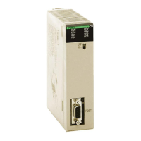
Mounting Procedure Mount the CJ1W-PRM21 PROFIBUS-DP Master Unit to the PLC using the fol-
lowing procedure.
1. Carefully align the connectors to mount the PROFIBUS-DP Master Unit.
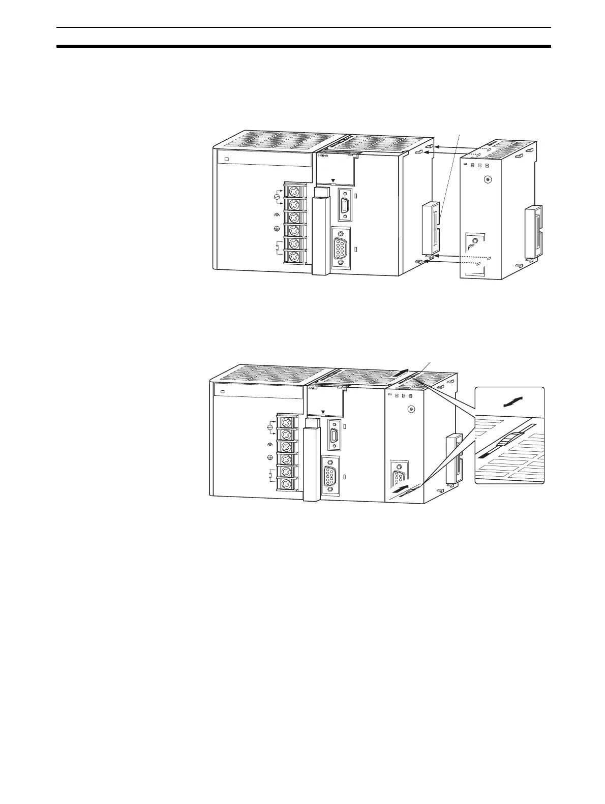
2. Move the yellow sliders on the top and bottom of the Unit until they click
into position, to lock.
Note If the sliders are not securely locked, the PROFIBUS-DP Master Unit func-
tions may not operate correctly.
To dismount the Unit, move the sliders to the “Release” direction.
2-3 Initial Setup Procedure
After mounting the PROFIBUS-DP Master unit to its PLC System, the follow-
ing Initial Setup Procedure must be applied to allow the Unit to start up prop-
erly and to be configured for operation.
• A unique unit number must be selected, before the PLC’s power supply is
turned on.
• An I/O table must be created in the PLC, in order to register the Unit on
the PLC CPU.
P
A205R
PO
W
E
R
IN
P
U
T
A
C
1
0
0
-2
4
0
V
L2/N
L1
D
C
2
4
V
A
C
2
4
0
V
O
U
T
P
U
T
R
U
N
PERIPHERAL
E
R
R
/A
L
M
R
U
N
IN
H
C
O
M
M
P
R
P
H
L
C
O
N
T
R
O
LLE
R
CJ1G-CPU44
SYSMAC
P
R
O
G
R
A
M
M
A
B
L
E
PORT
O
P
E
N
B
U
S
Y
M
C
P
W
R
B
F
B
S
T
N
O
.
U
N
IT
E
R
H
0
1
2
3
4
5
6
7
8
9
A
B
C
D
E
F
E
R
C
R
U
N
PRM21
C
O
M
M
PRM
Connector
BUS
PA205R
POWER
IN
P
U
T
A
C
1
0
0
-2
4
0
V
L
2
/N
L
1
D
C
2
4
V
A
C
2
4
0
V
O
U
T
P
U
T
R
U
N
PERIPHE
RAL
E
R
R
/
A
L
M
R
U
N
I
N
H
C
O
M
M
P
R
P
H
L
C
O
N
T
R
O
L
L
E
R
CJ1G-CPU44
SYSMAC
P
R
O
G
R
A
M
M
A
B
L
E
P
O
R
T
O
P
E
N
B
U
S
Y
M
C
P
W
R
B
F
BST
N
O
.
U
N
IT
ERH
0
1
2
3
4
5
6
7
8
9
A
B
C
D
E
F
ERC
R
U
N
PR
M
21
C
O
M
M
P
R
M
BUS
B
U
S
Slider
Release
Lock