155
Appendix
Note The Device related diagnostics as defined above is according to the PROFIBUS-DPV0 standard. With
the release of the PROFIBUS-DPV1 standard, the Device related diagnostics contents has been re-
defined to accommodate diagnostics from slave stations supporting PROFIBUS-DPV1.
Module Related Diagnostics
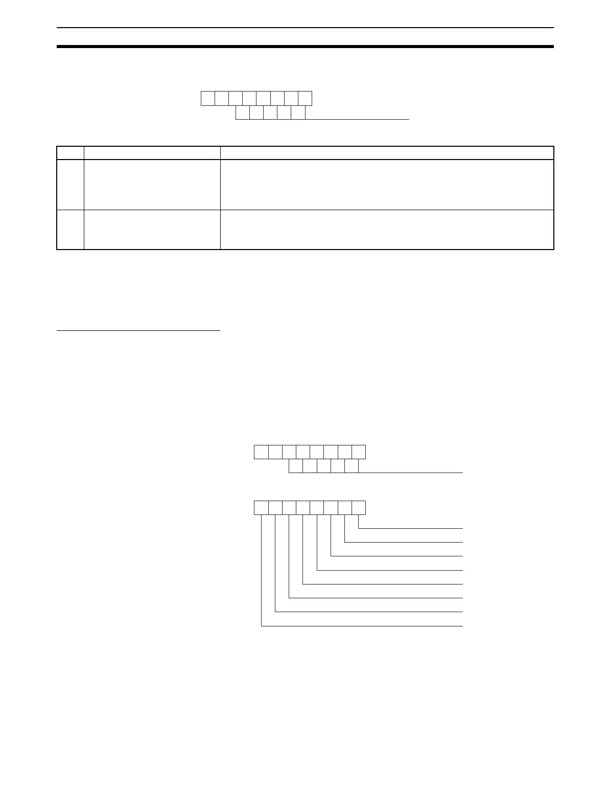
The Module or Identifier related diagnostics data block consist of a header byte followed by one or more bytes
containing flags, which indicate if there is diagnostics pending related to the I/O Configuration modules. Each
flag is related to the corresponding I/O module, defined during configuration. Non-used flags are always set to
0.
The figure below shows the header byte, and one module diagnostics byte. Depending on the number of I/O
modules configured, there may be more bytes.
Bit Name Description
00
~
05
Block length These bits contain the length of the Device related diagnostics data block, includ-
ing the header byte. The Device diagnostics will follow this header byte.
Maximum length of the block, including the header is 63 bytes.
Interpretation of the diagnostics bytes in this block is device dependent.
06
~
07
Reserved Fixed to 00.
The combination of bit 6 and 7 indicate the type of diagnostics, i.e. 00 indicates
Device related diagnostics data.
0 0
76543210
Block Length
0 1
76543210
Block Length
Header Byte
Module Diagnostics Byte
76543210
Module 0 Diagnostics
Module 1 Diagnostics
Module 2 Diagnostics
Module 3 Diagnostics
Module 4 Diagnostics
Module 5 Diagnostics
Module 6 Diagnostics
Module 7 Diagnostics