11
PROFIBUS-DP Master Unit
Section 1-3
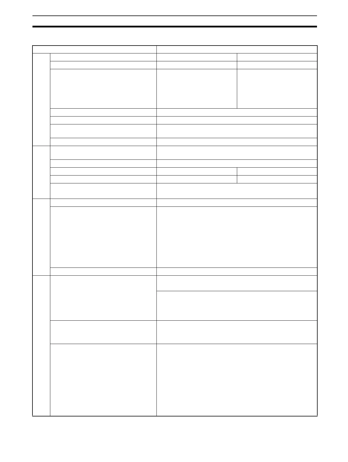
Functional Specifications
Item Specification
PLC types
PROFIBUS-DP Master Unit types CS1W-PRM21 CJ1W-PRM21
Applicable PLC series CS-series CJ-series
Mounting position • CPU Rack,
• CS Expansion Rack (Not in-
cluding a C200H Expansion
I/O Rack or SYSMAC BUS
Slave Rack.)
•CS1D Duplex
•CPU Rack,
• CJ1 Expansion Rack
Unit classification CPU Bus Unit
Applicable unit numbers 0 to F (Hex)
Maximum number of Units that can be
mounted per PLC
16
Current consumption 400 mA max at 5 Vdc
Environment
Ambient temperature Operating: 0 to 55°C
Storage: –20 to 75°C
Humidity 10% to 90% (with no condensation)
Dimensions (W x H x D) 35 x 130 x 101 mm 31 x 90 x 65 mm
Weight 187g (typical) 100g (typical)
Conformance to EMC and environmental
standards
EN 61000-6-2:2001
EN61131-2:1994+a12:2000
Front case
Settings Unit Number rotary switch, range: 0 ~ F (Hex)
Indicators 7 LEDs, indicating Unit status and PROFIBUS status:
Unit status: RUN (Green LED)
ERC (Red LED)
Host PLC status: ERH (Red LED)
Configuration status: PRM (Green LED)
PROFIBUS status: BST (Green LED)
COMM (Green LED)
BF (Red LED)
PROFIBUS Connector 9-pin sub-D female connector (#4/40 UNC thread)
Memory area allocation
CIO Area words allocated for the CPU Bus
Unit
Fixed allocation of 25 words per Unit.
CIO 1500 + (25 x Unit number)
CIO words provide:
• 2 words for software switches
• 1 word for the Global_Control
• 21 words for the Unit and Slave statuses
DM Area words allocated for the CPU Bus
Unit.
Fixed allocation of 100 words per Unit.
DM 30000 + (100 x Unit number)
DM Area allocated to the Unit is reserved for future use.
I/O Data allocations Maximum total size: 7168 words
I/O Data words can be allocated to up to 2 input areas and 2 output
areas
Input areas and output areas can be mapped to
•CIO Areas
• DM Areas
• WR Areas
• HR Areas
• EM banks
Mapping must be defined through Configurator