CHAPTER 6 CALIBRATION
E5GN
6–6
(6) Press the key to set the E5GN to the state on the left.
Set STV to Ć9mV".
Allow the count value on the No.2 display to fully stabilize, then press
the key to temporarily register the calibration setup. (Input types
0, 2, 5, 6, 8 : Go to step 11.)
(7) Press the key. The No.2 display changes to the state on the left
when the input type is 1, 3, 4, 7, 9, 10, 11, 12, 13, 14 or 15.
(8) Set STV to 54mV".
Allow the count value on the No.2 display to fully stabilize, then press
the key to temporarily register the calibration setup.
(9) Press the key. The No.2 display changes to the state on the left
when the input type is 1, 3, 4, 7, 9, 10, 11, 12, 13, 14 or 15. Set STV to
Ć9mV".
(10) Allow the count value on the No.2 display to fully stabilize, then press
the key to temporarily register the calibration setup.
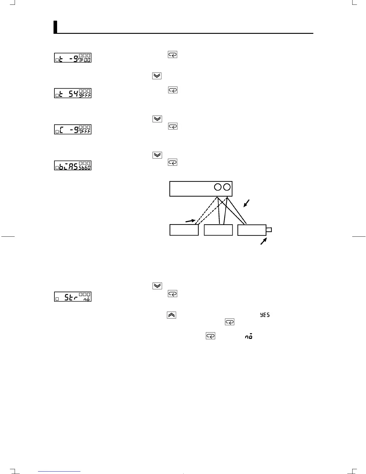
(11) Press the key to set the E5GN to the state on the left.
(12) Change the wiring as follows:
Open in non-connected state
Short
Compensating conductor of currently
selected thermocouple
Use K thermocouple compensating
conductor for E, R, S and B
thermocouples or non-contact
temperature sensor.
Zero
controller
STV DMM
OUTPUT
INPUT
-
+
E5GN
89
Disconnect the STV to enable the thermocouple of the cold junction
compensator. When doing this, be sure to disconnect the wiring on the
STV side.
(13) Allow the count value on the No.2 display to fully stabilize, then press
the
key to temporarily register the calibration setup.
(14) Press the key. The No.2 display changes to the state on the left.
Note that the data to be temporarily registered is not displayed when
it is not entirely prepared.
Press the key. The No.2 display changes to ". Release the key
and wait two seconds or press the key. This stores the temporarily
registered calibration data to EEPROM. Data will not be stored to
memory if you press the key with " displayed on the No.2
display.
(15) The calibration mode is quit by turning the power OFF.