CHAPTER 2 PREPARATIONS
E5GN
2–4
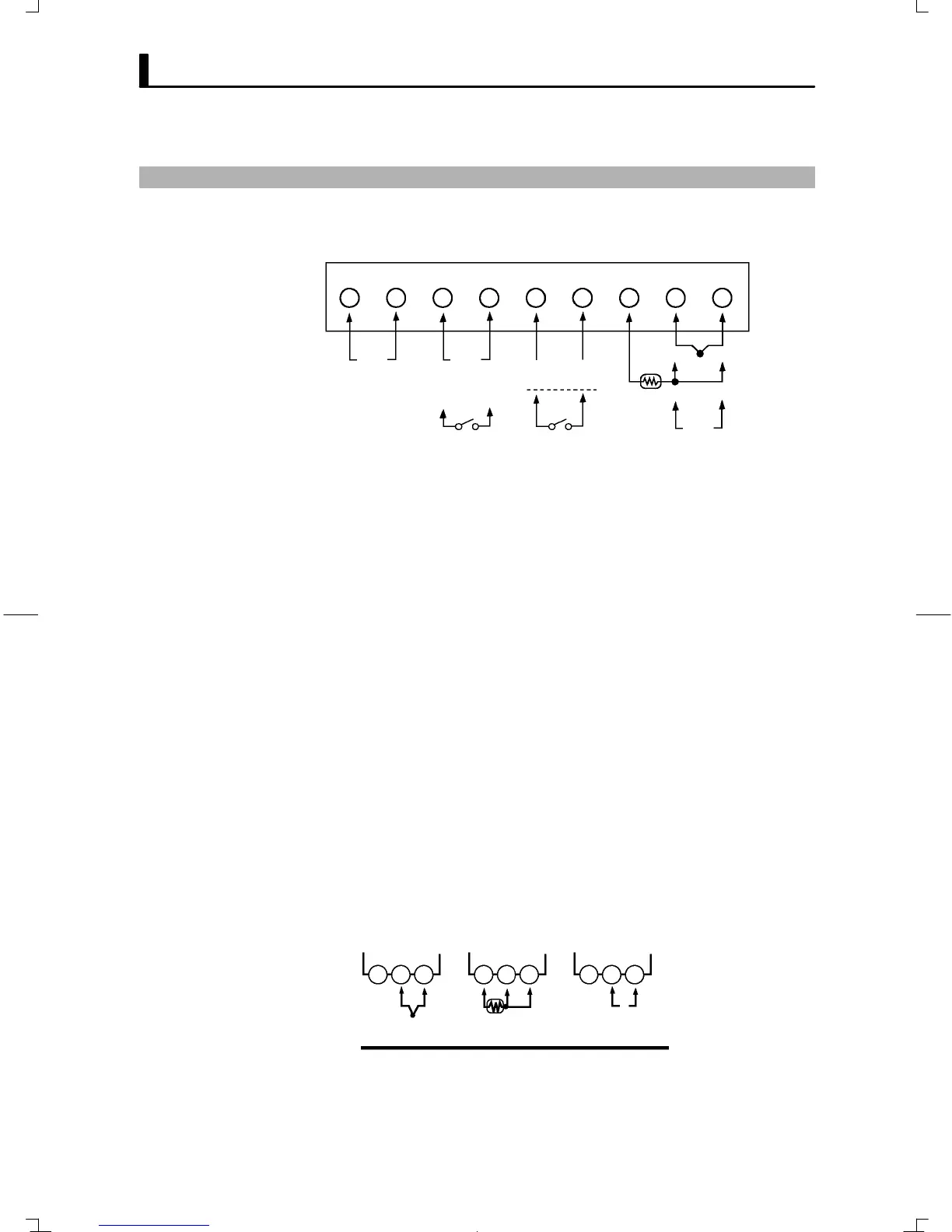
2.2 Wiring Terminals
E5GN
123456789
Input power
supply
100 to 240 VAC
24 VAC/DC
+ –
– +
ABB
TC
PT
Control output
Voltage output
DC12V 21mA
Relay output
(OUT1)
Alarm output 1/Control
output 2/Input error
(ALM1/OUT2)
Analog input
Communications
specifications
BA
Ă• Separate input leads and power lines in order to protect the controller
and its lines from external noise.
Ă• Use AWG24 to AWG14 leads for terminal Nos.1 to 6 and AWG28 to
AWG22 leads for terminal Nos.7 to 9.
Ă• Tighten the terminal screws using a torque no greater than 0.24 Nm
(2.5kgfcm) for terminal Nos.1 to 6, and a torque no greater than 0.13
Nm (1.4kgfcm) for terminal Nos.7 to 9.
JWiring
Ă• Connect to terminal Nos.1 and 2. The power supply specifications are as
follows:
100 to 240 VAC, 50/60 Hz, 7 VA
or
24 VAC, 50/60 Hz, 4 VA
24 VDC, 2.5 W (no polarity)
Ă• Standard insulation is applied to the power supply I/O sections. If reinĆ
forced insulation is required, connect the input and output terminals to
a device without any exposed currentĆcarrying parts or to a device with
standard insulation suitable for the maximum operating voltage of the
power supply I/O section.
Ă• Connect to terminal Nos.7 to 9 as follows according to the input type.
789 789 789
– + – +
V
ABB
Thermocouple
Platinum resistance
thermometer
Analog input
E5GN-jjjj
JTerminal
arrangement
JPrecautions
when wiring
F Power supply
F Input