2.2Wiring Terminals
E5GN
2–5
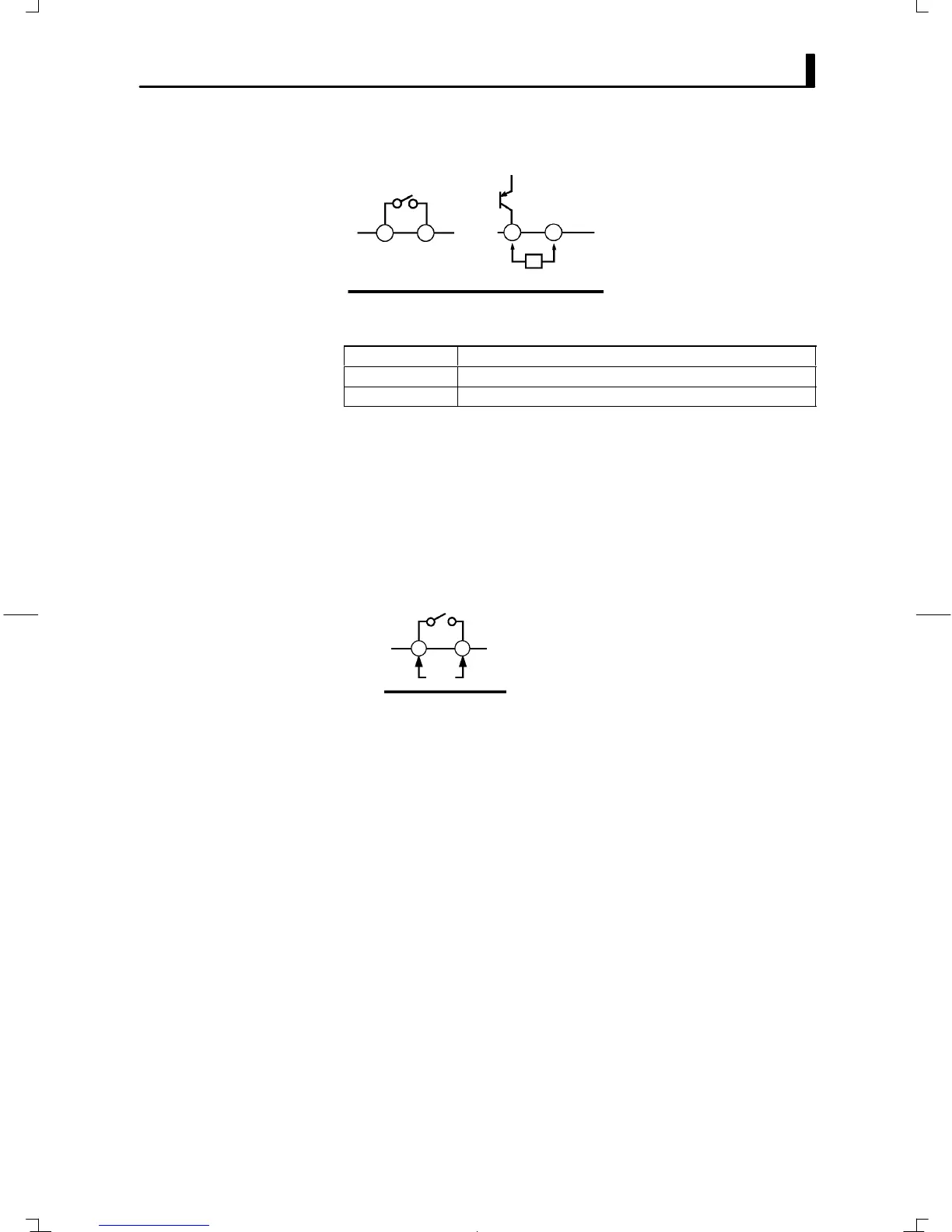
Ă• Terminal Nos.3 and 4 are for control output. The following diagram
shows the available outputs and their internal equalizing circuits.
34 34
GND
+V
+ –
Relay output
E5GN-jjjj
L
Voltage output
Ă• The following table shows the specifications for each output unit.
Output type Specifications
Relay 250 VAC, 2A, electrical life: 100,000 operations
Voltage (PNP) PNP type, 12 VDC, 21 mA (with short-circuit protection)
Ă• The voltage output (control output) is not electrically insulated from the
internal circuits. When using a grounding thermocouple, do not connect
the control output terminals to the ground. If the control output termiĆ
nals are connected to the ground, errors will occur in the measured temĆ
perature values as a result of leakage current.
Ă• On the E5GNĆj1j, alarm output (ALM) is across terminal Nos.5 and 6.
Ă• The following diagram shows the internal equalizing circuits for alarm
output.
Ă• When the input error output is set to ON", alarm output 1 turns ON
when an input error occurs.
56
E5GN-j1j
ALM1/OUT2/Input error
Ă• Relay specifications are as follows:
SPSTĆNO, 250 VAC, 1 A
F Control output
F Alarm output/
cooling output