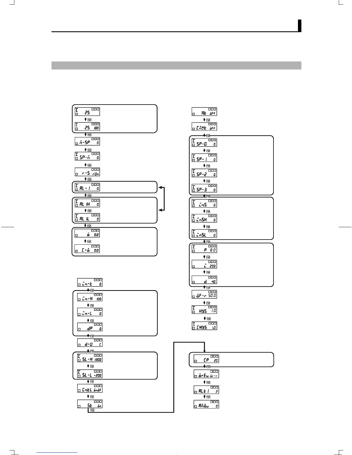
PARAMETER FLOW
E5GN
A–11
PARAMETER FLOW
Ă• If you press the mode key at the last parameter in each level, you return
to the top parameter in that level.
Operation level
PV
PV/SP
Add in the
“additional PV
display”
parameter.
MultiĆSP
Set point during SP ramp
Run/stop
Alarm value 1
UpperĆlimit alarm value 1
LowerĆlimit alarm value 1
Set either
of these
parameters.
MV monitor (OUT1)
Initial setting level
Input type
Scaling upper limit
0 to 50 mV
Scaling lower limit
Decimal point
_C/_F selection
Set point upper limit
Set point lower limit
PID / ON/OFF
ST
Control period (heat)
Alarm 1 type
Move to advanced
function setting level
Set the pulse output cycle.
Control the manipulated variable accord-
ing to the increase/decrease in the PV.
Number of digits displayed
past decimal point
Limit the set point.
Select the control system.
Self-tuning
Select the alarm mode.
Hysteresi (OUT1)
Adjustment level
AT execute/cancel
Communications writing
Set point 0
Set point 1
Set points
used by
multi-SP
Temperature input shift
1-point shift
2-point shift
Proportional band
PID
settings
Manual reset value
Auto-tuning
Enable or disable writing by commu-
nications.
Set point 2
Set point 3
LowerĆlimit temperaĆ
ture input shift value
UpperĆlimit temperaĆ
ture input shift value
Derivative time
Integral time
Clear the offset during
stabilization of P or PD control.
P
I
D
Direct/reverse operation
MV monitor (OUT2)
Hysteresi (OUT2)