CHAPTER 2 PREPARATIONS
E5GN
2–2
2.1 Installation
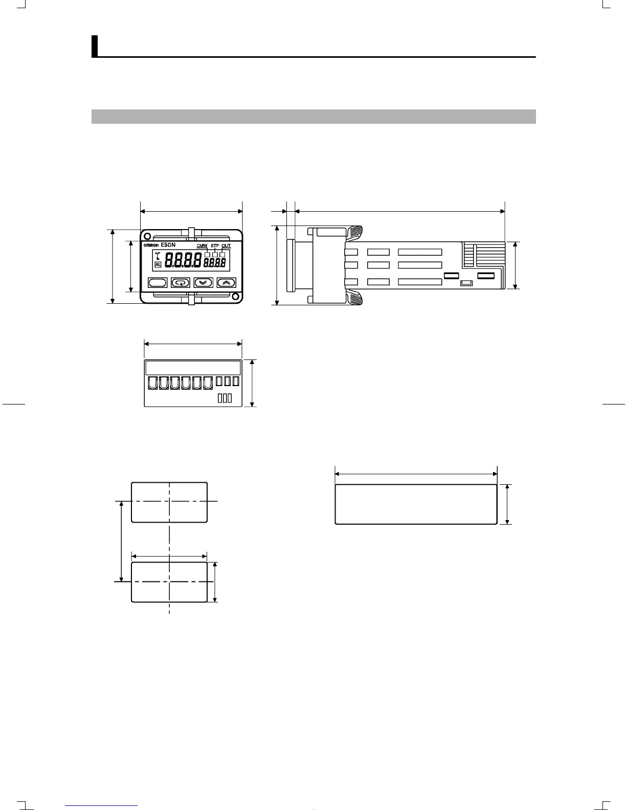
JDimensions
Ă• External dimensions (Unit: mm)
* When carrying out maintenance on the E5GN, only the terminal plate
can be drawn out with the terminal leads still attached.
48 3 100
44.8
35
24
(36.8)
22
22
JPanel cutout
(48number of units -2.5)
When mounted separately (unit : mm) When group-mounted (unit: mm)
+1.0
0
45
+0.6
0
22
+0.3
0
22
+0.3
0
60 min.
Ă• Insert the controller through the hole in the panel from the front, and
push the adapter on from the rear. Push the adapter up to the back of the
panel ensuring that the controller is pushed all the way in, removing any
gap between the controller, panel and adapter. Finally use the two
screws on the adapter to secure the unit in place.
Ă• To mount the E5GN so that it is waterproof, insert the waterproof packĆ
ing onto the E5GN.
Ă• When two or more E5GNs are mounted, make sure that the surrounding
temperature does not exceed the allowable operating temperature given
in the specifications.
F E5GN