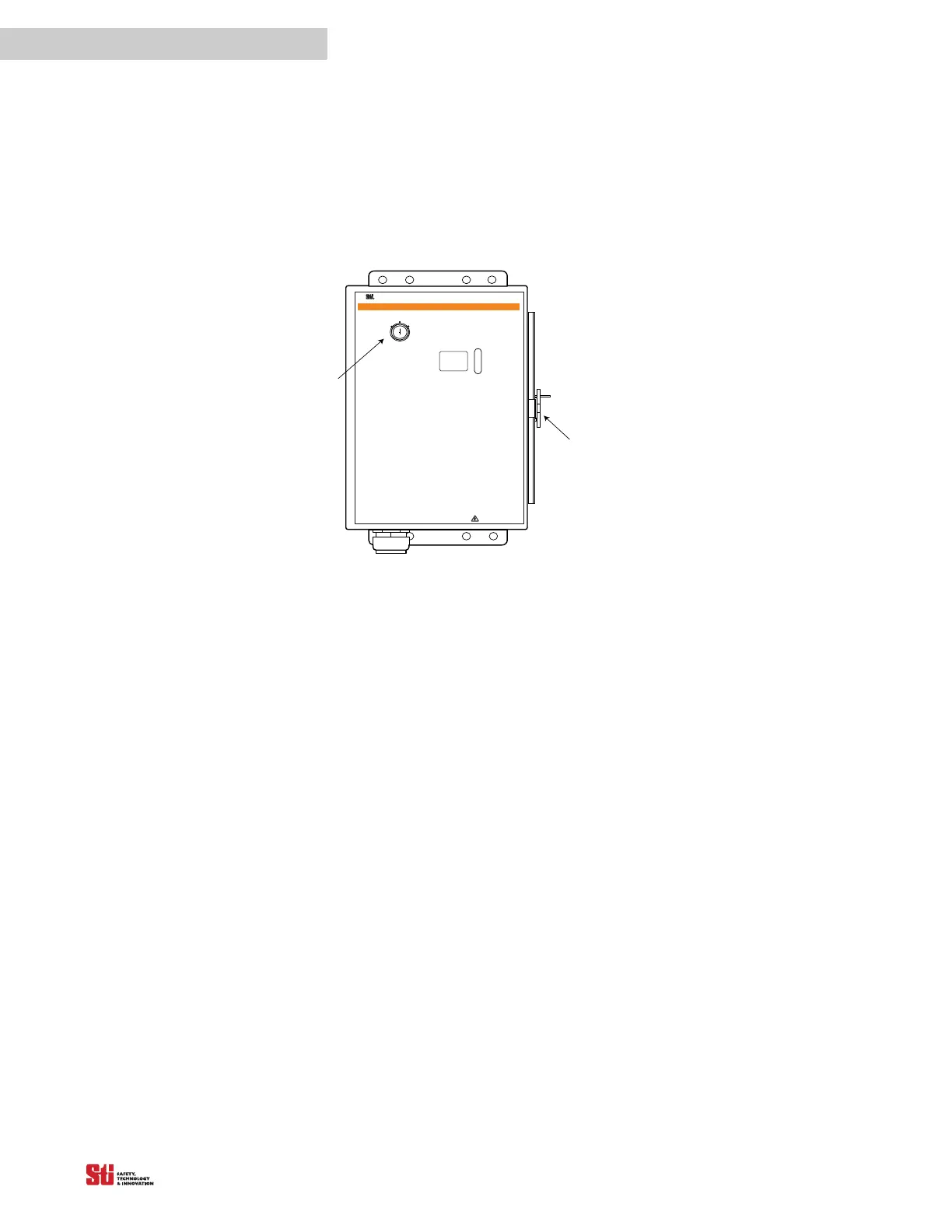
possession of the key to the padlock, or to the optional Program/Start keyswitch.
STOP
RUN
RUN
START
IN TERLO CK
FB/ C S
W A R N I N G
Scientific Technologies Inc, Fremont, CA 94555 U. S. A.
R
!
T
o test the l ight c urtai n, us e the appropri ate S T I -
suppli ed test objec t, or pr operly siz ed opaque cyl indri cal
object.
I f y ou are us ing the C hannel Sel ect or F loati ng
B lanki ng features and the object to be ignored does not
compl etely prevent ac cess to the haz ardous ar ea, ei ther
(1) use a mechanical guard or other means to block
access or (2) increase the minimum safe distance and
use a l arger test obj ect di ameter as expl ained in the
Installation and Operating Manual.
1. Di sabl e the machine. Pow er on the l ight cur tain.
2. I nspect the mac hine to ens ure entry to the
hazardous area is only through the light curtain sensing
fi eld. I f not, addi tional guarding, incl uding mechanical
barriers may be required.
3. Veri fy that the mounti ng distanc e of the l ight
curta in i s equal to or gr eater than the mini mum safe
dis tance fr om the hazardous point. Ens ure the operator
is not able to stand undetec ted between the li ght curtai n
and the hazard.
4. Chec k f or exter nal dama ge to the li ght curtai n,
the machi ne, elec trical c ables and wi ring.
5. I nter rupt the sensing fi eld with the
test
object t
o check the ef fec tiv eness of the l ight c urtai n.
M ove the test obj ect ins ide the peri meter ( along the top,
Do Not Remove Or Cover This L abel
http:/ / www.sti.com1/ 888/ 510-4357
ST I Label P/N 28621-0010 re
T
EST
P
ROCEDURE
sides and bottom) of the sensing field and up and down
through the center of the s ensi ng fi el d. V eri f y that the
R ed in dica tor i s ON and the G r een indi cator is OF F whil e
the test object is anywhere in the sensing field.
watch f or any unpr otected access to the poi nt of hazar d.
6. Sta rt the machi ne. I nterrupt the sensing f ield
wi th the test objec t. T he machine should s top
immediately. Never insert the test object into the
dangerous par ts of the machine! W ith the mac hine at
rest, inter rupt the sens ing fi el d with the test obj ect.
that the machi ne wil l not star t with the test obj ect in the
sensing field.
7. E nsure the braking and machine stop systems
are working properly in accordance with the machine
manufa cturer Õs requi rements. I f the machi ne does not
stop fast enough, adjust the braking system or increase
the dis tance f rom the li ght curtain to the poi nt hazard.
8. If the saf ety dev ices or machi ne fa il any of these
tests, do not run the machine. I mmediatel y l ock out the
machi ne to prevent i ts use and noti fy the superv isor
9. If the Channel Select is reprogrammed or
dis abled, y ou must repeat these tes t procedures.
10 . Close and l ock t he light cur ta i n contr
encl osu re d oor, i f a ppl ica bl e.
Diagnostic Codes:
00 Normal Operation
01 Normal Operation, waiting for Start signal
02 Normal Operation, Floating Blanking active
03 Normal Operation, Exact Channel Select active
04 Normal Operation, Exact Channel Select and
Floating Blanking a ctive
20 General DIP switch fault
21 Invalid switch setting
22 DIP switch settings changed during operation
23 Invalid C hannel Select or M PCE switch settings
30 G enera l Safety O utput fault
40 General MPCE fault
41 MPC E open before sa fety output (OS SD) activation
43 MPC E open when power is applied
50 Internal controller fault
51 Receiver fault
52 Transmitter fault
53 Transmitter and receiver length mismatch or transmitter
and r eceiver not connected
59 24 VDC power supply fault
Clasp
PROG RAM
Opti onal
Keyswitch