. . . . .
OMRON SCIENTIFIC TECHNOLOGIES INC.
Fremont CA USA
Tel: 1/888/510-4357 in USA and Canada
© OSTI 1209 PN99584-0050 Rev. E
Original Instructions
95
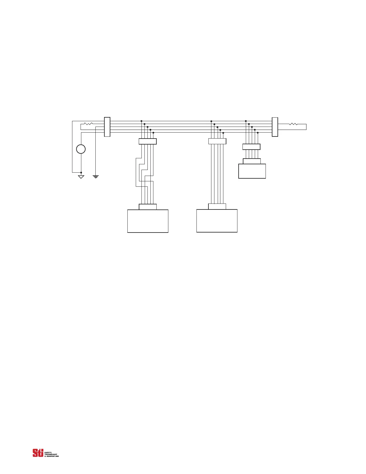
C.3 BASIC DEVICENET NETWORK CONNECTIONS
The figure below illustrates the basic wiring principles used to integrate OMRON STI products into a
small DeviceNet network. In this basic network, Phoenix style screw connectors and M12 micro-style
connectors are used to connect this communication system together. Our LCM-2XX series controllers
use the M12 micro-style connectors conforming to the DeviceNet standard.
LCM-2XX, LCM-Nema
wi th
DeviceNet option
LCM-2 Series
wi th
DeviceNet option
12
3
45
12
3
45
12
3
45
1716
15
1413
M12, Micro-style
Connector
Screw
Connector
11 to 24 VDC
Power S upply
Earth
Ground
V1
+
–
121
1
2
3
4
5
Screw
Connectors
Screw
Connectors
DeviceNet Trunk End
DeviceNet Trunk End
1
2
3
4
5
121
Screw
Connectors
12
3
45
12
3
45
Master
Controller
DeviceNet5-pin/Conductor
Female Micro style (M12) cable
DeviceNet5-pin/Conductor
Female Micro style (M12) cable
Figure C-1 Basic DeviceNet configuration
C.4 LCM-2XX SERIES INTERNAL D-NET WIRE COLORS AND PIN OUTS
The following internal connections are in compliance with the electrical requirements of the DeviceNet
standard however, the internal connections of these Nema controllers do not follow the wire insulation
color code as outlined by that standard.
When using the Nema type enclosure the internal DeviceNet Interface (Daughter Board) is connected
to a pre-m
anufactured 5-wire
M12 micro-style connector to a 5-pin Phoenix Style screw connector.
The M12 male connector as shown in figure 2, provides the external connection for the network.
C.4.1 SCREW CONNECTORS FOR LCM-2XX SERIES D-NET INTERFACE MODULE
The following figure illustrates the wire insulation colors and pin outs for the screw connectors on the
DeviceNet Interface (Daughter Board).
Shown are the following designations for the internal screw type connector:
1.V_: (blue)
2.CAN_Low: (gray)
3.Drain: (brown)
4.CAN_High: (black)
5.V+: (white)