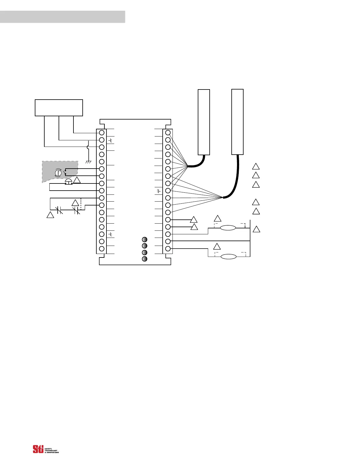
FGR series relays provide force-guided relay outputs for machine control. See Figure 10-3 for the
preferred connection method using two force-guided relays.
OS S D
RTN
MPCE
AUX 1
OUT
GRAY
WHITE
DATA L
CAN V-
START
RETURN
PINK
BLACK
+2 4V DC
BLUE
LCM Controller
OR ANGE
BROWN
OSSD1
0 VDC
START
MPCE
RETURN
DATA H
CAN V+
OS S D 2
AUX 2
OUT
YELLOW
RED
FB/CS
Interlock
Stop
Run
Receiver
Transmitter
MPCE 2
MPCE 1
+24 VDC EARTH 0 VDC
POWER SUPPLY
1
Auxiliary Output 1: NPN, 100 mA max. ,
30 VDC max.
Auxiliary Output 2: PNP, 500 mA max. ,
Vsupply -2V
For the purpos e of bench testi ng prior to
installation, the user may select MPCE OFF.
In thi s case, the MPCE i nput must be connected
to MPCE RETURN.
MPCE monitoring must be used when
force-guided relays are used as the Final
Switching Devices. Connect the MPCE output
to MPCE R ETURN through the NC contacts.
2
3
4
5
1
2
3
4
5
If remote S TAR T is not used, connect STAR T
output to STAR T R ETURN.
2. 25A 24 VDC 54VA
34
33
32
31
30
29
28
27
26
25
24
23
22
21
20
19
18
TAN
VIOLET
The MPCE coi l s must be s uppres s ed wi th the
arc suppressor provided in the documentation
kit.
6
6
6
Arc Suppressor
MPCE 1
Arc Suppressor
MPCE 2
1
2
3
4
5
6
7
8
9
10
11
12
13
14
15
16
17
Must be accessible only
by key.
PROGRAM